38 ford alternator wiring diagram internal regulator
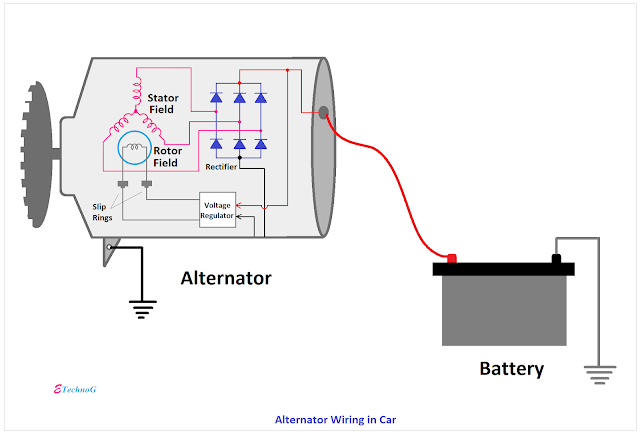
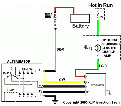
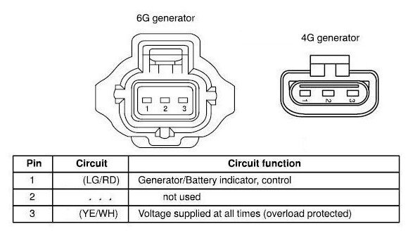
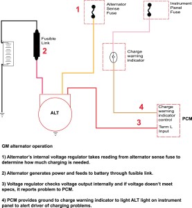
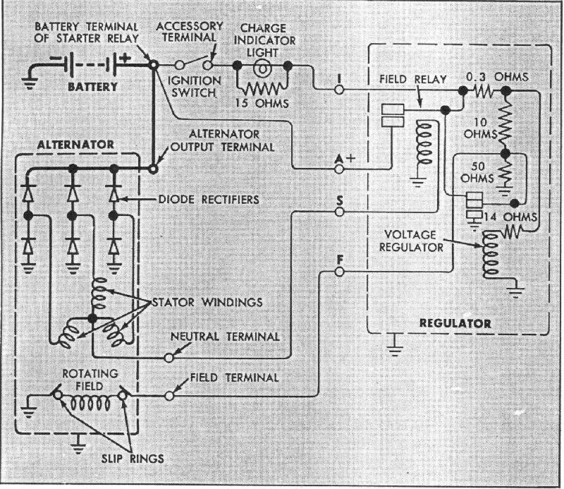
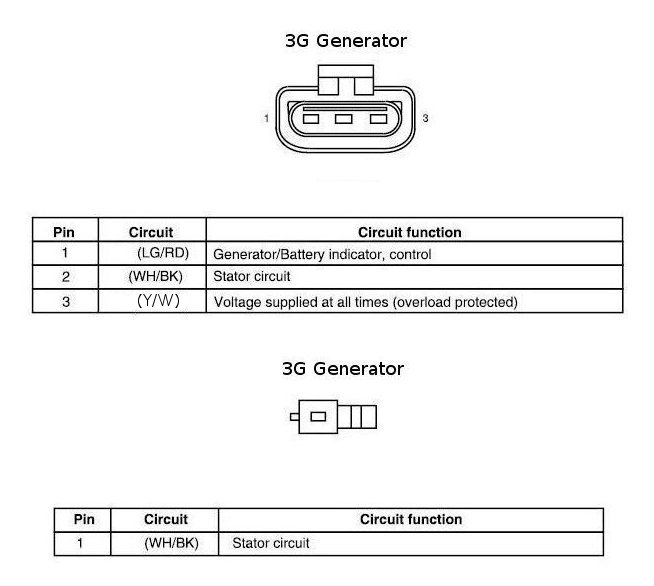
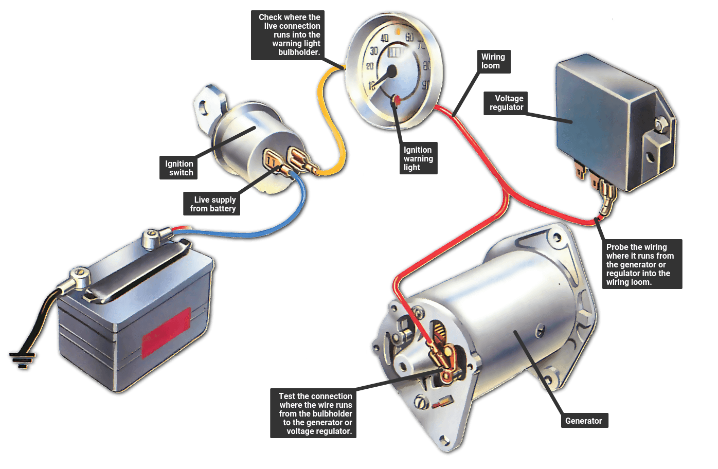
A typical 3-wire alternator wiring diagram with an internal voltage regulator. Computer-Controlled Voltage Regulation. Many late-model vehicles use the engine computer, which is often referred to as the powertrain control module (PCM), to control alternator output. Most modules use an internal driver to turn the alternator’s field circuit on ... The wiring was simple and the internal regulator eliminates some of the clutter. I reused the original "Gen" light as the warning light, ran the heavy "bat" terminal to the starter solenoid battery side and a smaller third wire on the alternator was spliced in where i'd joined the yellow wires together with a butt connector at the old regulator ...
Gm Alternator Wiring Diagram Internal Regulator New Fresh 3 Wire – Gm Alternator Wiring Diagram Internal Regulator. Wiring Diagram arrives with a number of easy to adhere to Wiring Diagram Directions. It really is meant to assist all the average person in creating a suitable program. These instructions will be easy to understand and apply.
Ford alternator wiring diagram internal regulator
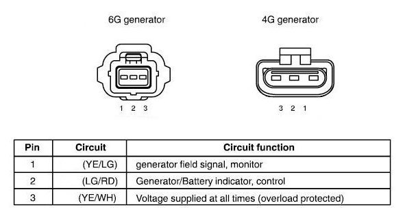
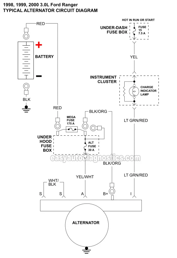
Ford Alternator Wiring Diagram Internal Regulator – ford alternator wiring diagram internal regulator, Every electrical arrangement is made up of various diverse parts. Each part ought to be set and connected with different parts in specific manner. If not, the structure will not work as it ought to be. Ford alternator wiring diagram internal regulator. Ford alternator wiring diagram. Assortment of ford one wire alternator wiring diagram. Basic schematic for wiring a ford alternator with external regulator with and without warning light. A number of posts on the back of the alternator are used to. Ford Hybrid 1-Wire Alternator Instructions FordHybridAlternators.pdf 1-Wire Alternator Installation. Alternator Tech Tip TechTip.pdf Loosen or tighten an alternator pulley nut. CS130 Alternators - 1-Wire or OEM CS130 Alternators.pdf GM 1987-94. CS130D Alternators - 1-Wire or OEM 8206_8242_Alternators.pdf 8206 and 8242 Alternators.
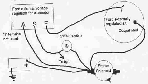
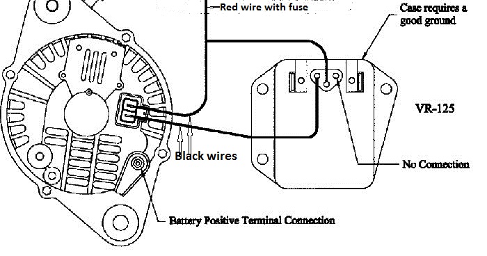
Ford alternator wiring diagram internal regulator. Locate a yellow wire if your alternator has a fourth terminal. If you do not have another wire, then ignore the terminal as your dashboard warning light is wired elsewhere. The fourth terminal is smaller than the others and so is the wire. Push the yellow wire onto the connector or place the eyelet over the terminal and screw in the small bolt ... Alright guys, in this video we install the new Alternator with the One Wire Conversion installed on the back in our ‘66 Mustang. This adds the voltage regul... Where can I find the internal schematic for the common Ford external alternator regulator, the one with I A S F terminals? I believe these type regulators were very common in the '80s. And also the internal wiring diagram for the alternator that went along with it (model ??). in todays video we cover how to diagnose a first gen ford alternator and test the alternator or voltage regulator.Tools used in the videoVolt meter: https://...
Ford Hybrid 1-Wire Alternator Instructions FordHybridAlternators.pdf 1-Wire Alternator Installation. Alternator Tech Tip TechTip.pdf Loosen or tighten an alternator pulley nut. CS130 Alternators - 1-Wire or OEM CS130 Alternators.pdf GM 1987-94. CS130D Alternators - 1-Wire or OEM 8206_8242_Alternators.pdf 8206 and 8242 Alternators. Ford alternator wiring diagram internal regulator. Ford alternator wiring diagram. Assortment of ford one wire alternator wiring diagram. Basic schematic for wiring a ford alternator with external regulator with and without warning light. A number of posts on the back of the alternator are used to. Ford Alternator Wiring Diagram Internal Regulator – ford alternator wiring diagram internal regulator, Every electrical arrangement is made up of various diverse parts. Each part ought to be set and connected with different parts in specific manner. If not, the structure will not work as it ought to be.












Comments
Post a Comment