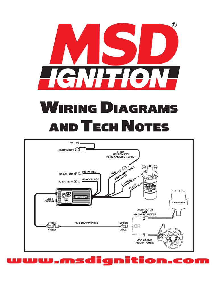
41 msd 7531 wiring diagram
Msd 7531 Wiring. Programmable digital-7 plus • Read online or download PDF • MSD Note : Solid core spark plug wires cannot be used with an MSD Ignition Control. Junior Member. Spooled up. OneFastFox's Avatar. Join Date: May Location : NC! Posts: Default MSD wiring/ transbrake wiring. The Ignition is supplied with wiring harnesses, mounting ... Msd Ignition Grid System Controller Only Pro Mag 12 20 44 7730. Pro mag 44 kill switch relay wiring msd amp generator electronic points box jumper wire on the tach converter pn 8132 7531 reva holley motor information help with how to properly a programmable digital shift light 8918 signal gmr pickup 7730 power grid system diagrams and tech notes ignition page 2 remote engine shut off ...
Wiring Diagrams FT450 Honda K20-24Version: 1.0 | Size: 0.92 MB FT550 8 Cyl Smart CoilVersion: 1.0 | Size: 0.52 MB FT550 6 Cyl Smart CoilVersion: 1.0 | Size: 0.51 MB ...
Msd 7531 wiring diagram
Re: msd 7531 with nitrous. #12. Post. by John_Heard » Thu Nov 05, 2015 3:02 pm. No, Dark Blue is the main reset, it's typically hooked up to a transbrake which will signal the start of the run. In your case I'd probably rig me up a switch and connect it to your brake light switch since your foot braking it. MSD Programmable Digital-7 CD Plus ignitions have an output power and Individual Cylinder Management timing system that are hard to beat. At the heart of these ignitions is a 15 MHz micro-controller that analyzes and manages every trigger signal. Their capacitive discharge circuits and state-of-the-art IGBT coil drivers work together to deliver ... MSD IGNITION • www.msdignition.com • (915) 857-5200 • FAX (915) 857-3344 Programmable Digital-7 Plus PN 7531 Parts Included: 1 - Ignition Control, PN 7531 1 - TI Pressure Gauge Harness 1 - MSD Pro-Data+ CD Rom
Msd 7531 wiring diagram. If you hire a professional to wire you car, I would expect that he documented what he did for you in a wiring diagram. Or at least tell you which of the MSD suggested wirings he used (as there are a number of alternatives in the wiring instructions). That is what I suggest you post for us to look at to help you diagnose your problem. Or at least tell you which of the MSD suggested wirings he used (as there are a number of alternatives in the wiring instructions). That is what I suggest you post for us to look at to help you diagnose your problem. This because wiring of the 7531 and programming of the same goes hand in hand. Wiring Diagram For Electric Shift To Msd 7531 Site. Page 1. FBIONĀDES. RACING PRODUCTS, INC. Biondo Racing Products Electric Solenoid Shifter (#ESS). Installation Instructions. Our electric solenoid WIRING DIAGRAMS. 1) When using an MSD RPM Activator Switch follow this diagram. Page 1 The SS5 solenoid shifter is designed to shift 2-speed ... wiring chart function pin wire color wire description notes output voltage can be calibrated via msd view . the default output voltage, 0-5v, corresponds to an afr (air fuel ratio) 8-18 of gasoline .a zero (0) volt reading is an afr of 8 and 5v is anafrof18. (2afrpervolts) output to a gauge or daqisanoption. power source
If you're a consummate engine tuner and know how to take advantage of minute changes in timing during a quarter-mile pass, then the Programmable Digital-7 Plus is the ignition for you! All of the standard programmable features such as Individual Cylinder Management, Step Retards, Rev Limits, Shift Points, and more are included in the Plus version but you also get more. Much, much more. A MAP ... Wiring diagram for electric shift to msd 7531 site. Gaggia accademia parts diagram. 7 pin pollak wiring diagram. Kenwood ddx271 wiring diagram. Vixen ooga horn wiring diagram. Wiring diagram for clarion vz400. Wiring diagram for john deere l120 lawn tractor. Ford solenoid 2701966 wiring diagram. 1) Connect step 1 retard pink wire (MSD 7531 box) to the output terminal of the relay that activates the nitrous or directly to the nitrous solenoid itself. 2) After opening the msd pro-data software on the laptop, I will open the data editor menu tree, scroll down to retards, click on step 1 retard, then program my 8* of timing there, ramping ... The MSD Programmable Digital-7 uses a high speed RISC microcontroller to ... WIRING. Ignition supply wire. Connects to battery positive (+) terminal or ...16 pages
That is why we have assembled the MSD Ignition Wiring Diagrams and Tech Notes ... PN 7531 only - OutCam: Select either a Cam Sync output or a Rev Limiting ...192 pages WIRING THE UNIT Follow the wiring diagram supplied. If your RPM switch or Timer supplies a "Normally Open Ground" connect the trigger wire from your device to post 86 on the relay. Supply post 87 and 85 with 12V+, with a 12 gauge wire. Connect post 30 to the solenoid. 7531 and msd 8 wiring diagrams. Jump to Latest Follow 1 - 19 of 19 Posts. jlawson · Registered. Joined Feb 23, 2007 · 98 Posts . Discussion Starter · #1 · Oct 31, 2009. does anybody have a wiring diagram to wire msd 7531 box to msd 8 with big stuff 3 any help will be appreciated thanx ... This file contains bidirectional Unicode text that may be interpreted or compiled differently than what appears below. To review, open the file in an editor that reveals hidden Unicode characters.
MSD 7531 and a Shifnoid electric shifter solenoid. Using a relay. Cant seem to get it working. I would like to use the yellow wire and not the brn/wht. Please help. Spring Loaded Shifnoid for PG forward pattern if that makes any difference. To wire the relay to your shifnoid will require a 5 pin relay.
A wiring diagram is a simplified standard pictorial representation of an electrical circuit. Msd 6ls wiring lsx mod motor and gen iii hemi tech. The wire descriptions follow in the chart on pages 2 and 3. Once loaded your monitor will have an msd graph view logo. And tech that is why we have assembled the msd ignition wiring diagrams and tech ...
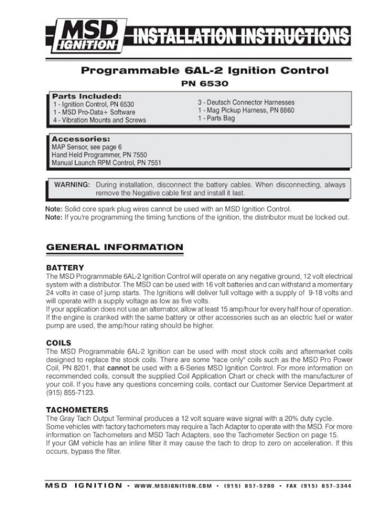
PN 7531. ONLINE PRODUCT REGISTRATION: Register your MSD product online and you'll be entered . in our monthly 8.5mm Super Conductor Spark Plug Wire give-away! Registering your product will help if there is ever a warranty issue with your product and helps the MSD R&D team create new products that you ask for! Go to www.msdignition.com ...
Msd 7531 Wiring Diagram. 15.04.2019 15.04.2019 0 Comments on Msd 7531 Wiring Diagram. Find MSD Programmable Digital-7 Plus CD Ignitions and get Free Shipping on with the Pro-Data Plus software, PC harness, vibrations mounts, and wiring. Is the coil diagram for the 6 series wiring, the same for a ? ...
This can be done using a 4 pole, Double-Throw switch for a dual mag installation or a 2 Pole, Double-Throw switch for a single mag installation (See wiring diagrams*). A word of caution here, extending magnetic pickup leads can introduce EMI (Electro magnetic Interference) or RF (Radio Interference) into the system, this can cause random ...
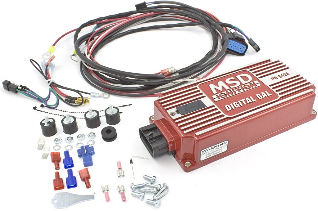
MSD • WWW.MSDPERFORMANCE.COM • (915) 857-5200 • FAX (915) 857-3344 Parts Included: 1 - Ignition Control, PN 7531 1 - MSD Pro-Data+ CD Rom 4 - Vibration Mounts & Screws 1 - Shielded Cam Sync Harness 1 - 9-Pin Computer Harness Accessories Hand Held Monitor, PN 7550 Inductive Cam Sync Pickup Kit, PN 7555
MSD IGNITION • www.msdignition.com • (915) 857-5200 • FAX (915) 857-3344. Accessories Dark Blue. This wire activates the Launch Rev Limit and is the main reset wire for several features of the Ignition. When 12 volts are applied to this wire it will activate the Launch Rev Limit. It also
For information on South Africa's response to COVID-19 please visit the COVID-19 Corona Virus South African Resource Portal.
MSD IGNITION • www.msdignition.com • (915) 857-5200 • FAX (915) 857-3344 Programmable Digital-7 Plus PN 7531 Parts Included: 1 - Ignition Control, PN 7531 1 - TI Pressure Gauge Harness 1 - MSD Pro-Data+ CD Rom
MSD Programmable Digital-7 CD Plus ignitions have an output power and Individual Cylinder Management timing system that are hard to beat. At the heart of these ignitions is a 15 MHz micro-controller that analyzes and manages every trigger signal. Their capacitive discharge circuits and state-of-the-art IGBT coil drivers work together to deliver ...
Re: msd 7531 with nitrous. #12. Post. by John_Heard » Thu Nov 05, 2015 3:02 pm. No, Dark Blue is the main reset, it's typically hooked up to a transbrake which will signal the start of the run. In your case I'd probably rig me up a switch and connect it to your brake light switch since your foot braking it.












Comments
Post a Comment