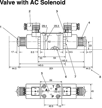
42 hydraulic solenoid valve wiring diagram
•Electrical power should be maintained on detented valves (spool code 3A). Detent only maintains start-up position of the valve. 31341 Friendship Drive, Magnolia, TX 77355 • Tel.: 281-259-7768 Fax: 281-259-7249 • www.hyvair.com D05 Series 35- Solenoid Operated Directional Valves Electrical Information Solenoid Coil Specifications Hydraulic solenoid selector dv50 instruction diagram summit hydraulics nachi fujikoshi corp product info equipment how to wire a valve 220v relay valves general electronics arduino forum detail hc connecting and ac power hydrawise wiring pump png 1323x760px area auto part fluid pack unit design dc with 3 diverter 13 gpm 12v plc controls molock directional control 2 spool… Read More »
Title: D03, D05 and D08 Solenoid Valves.pdf Author: marcus.kennedy Created Date: 12/2/2010 9:42:13 AM Keywords ()

Hydraulic solenoid valve wiring diagram
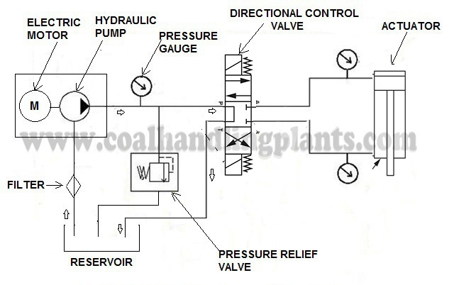
Hydraulic Solenoid Valve Wiring Diagram from i.ytimg.com Print the cabling diagram off plus use highlighters to be able to trace the circuit. When you make use of your finger or stick to the circuit together with your eyes, it is easy to mistrace the circuit. A single trick that I actually use is to print the same wiring diagram off twice. Before selecting hydraulic directional spool valves, it must be sure to choose appropriate spool valve in neutral position as per requirements of hydraulic system. For example: 1. Design pressure unloading circuit by spool function in neutral position to achieve energy savings. When H, F and G spool type in neutral position of 4way, 3postion directional spool valve, the oil fluid from pump ... Hydraulic solenoid Valve Wiring Diagram. Collection of hydraulic solenoid valve wiring diagram. A wiring diagram is a simplified standard pictorial representation of an electric circuit. It reveals the components of the circuit as streamlined shapes, as well as the power and also signal links in between the gadgets. A wiring diagram normally provides details about…
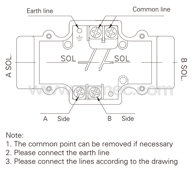
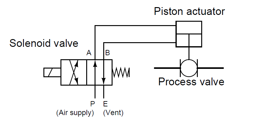
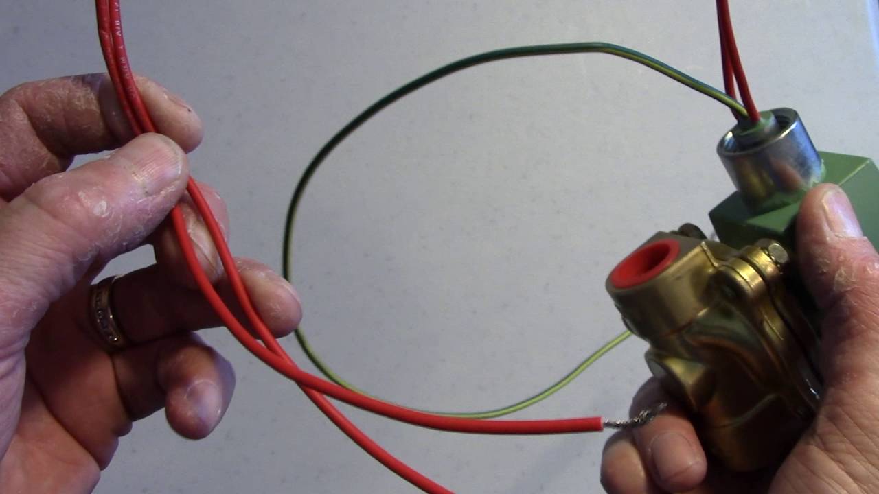
Hydraulic solenoid valve wiring diagram. Procedure on how to wire the electrical components in a solonoid valve, brought to you by http://stcvalve.us/CAUTION: Do not energize the coil before it is a... Hydraulic solenoid valves. The hydraulic solenoid valve is a directional control valve widely used in hydraulic systems to change, allow or restrict the flow of ... The wiring diagram of the solenoid valve is as below. Although the wiring of solenoid valve is simple, but poeple still encouter problems when wiring the solenoid valve to other devices. Here are some problems for your reference. 1. Is it that the solenoid valve on the pneumatic stop valve can be two-wired, three-wired or four-wired? ISARMATIC® HYDRAULIC UNIT PARTS DIAGRAM End Cap Motor Motor.combinations to direct hydraulic fluid to the snowplow lift and angle cylinders or back to the reservoir. Raise and angle functions require both the motor and solenoid cartridge valve (s) to activate, while the lower function only requires activation of a solenoid cartridge valve.
Solenoid lsarmatjc~ Mark ila Hydraulic System Parts Diagram. 39 Your WESTERN Snowplow Solenoid ISAÀMATlC~ Mark ilia Hydraulio. Unit has a serial. Western Controls and Wiring for all Western Snowplows and Salt/Sand Spreaders. HYDRAULIC HOSES On this page you will find access to all the Western plow controls and wiring that we SOLENOID CONTROL ... Hydraulic solenoid Valve Wiring Diagram. Collection of hydraulic solenoid valve wiring diagram. A wiring diagram is a simplified standard pictorial representation of an electric circuit. It reveals the components of the circuit as streamlined shapes, as well as the power and also signal links in between the gadgets. A wiring diagram normally provides details about… Before selecting hydraulic directional spool valves, it must be sure to choose appropriate spool valve in neutral position as per requirements of hydraulic system. For example: 1. Design pressure unloading circuit by spool function in neutral position to achieve energy savings. When H, F and G spool type in neutral position of 4way, 3postion directional spool valve, the oil fluid from pump ... Hydraulic Solenoid Valve Wiring Diagram from i.ytimg.com Print the cabling diagram off plus use highlighters to be able to trace the circuit. When you make use of your finger or stick to the circuit together with your eyes, it is easy to mistrace the circuit. A single trick that I actually use is to print the same wiring diagram off twice.
Uniair module components (1-Solenoid valve, 2-Hydraulic brake ...

How to Wire Hydraulic Power Pack,Power Unit Diagram Design

China Anlite Hydraulic Solenoid Valve Coil with High Quality ...

Product Detail

24vdc Airtac Solenoid Valve 4v210-08 Manual Wiring Diagram 4v210 08 - Buy Pneumatic Solenoid Valve,5 2 Way Solenoid Valve,Pneumatic Air Valve Product ...
Solenoid Valve Wiring
Vickers DG4V Solenoid Directional Valve from China ...
Pneumatic Circuit Symbols Explained |Library.AutomationDirect

How to Wire Hydraulic Power Pack,Power Unit Diagram Design
Hydraulic Solenoid Valve 12 Volt Lb-a5024 Rsv1751es 12v Shut ...
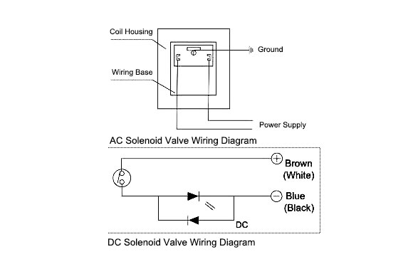
How to Wire a Solenoid Valve?
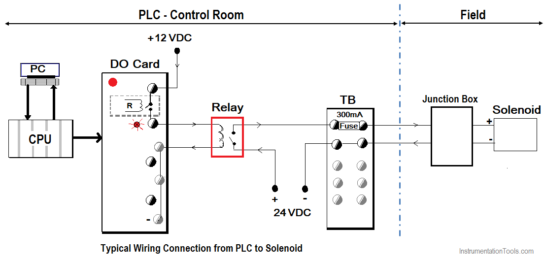
How to Connect a Solenoid Valve with PLC? - InstrumentationTools
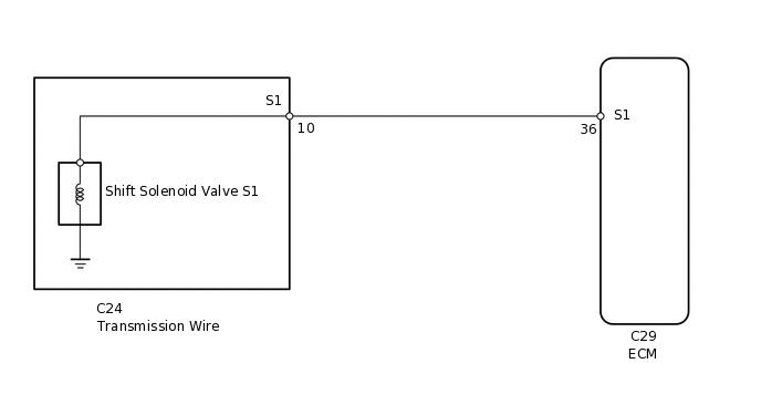
AUTOMATIC TRANSMISSION SYSTEM, Diagnostic DTC:P0973 and P0974

EMERSON – ASCO Solenoid Valve Coil 400 425 117, Series 272/374 230 V
NACHI-FUJIKOSHI CORP. / Product Info. / Hydraulic Equipment

Mobile hydraulics troubleshooting, Pt. 2

File:Solenoid Valve.svg - Wikipedia
Rexroth Solenoid Coil For Sale | AC, DC | Rexroth Solenoid ...

Integral Position Sensor Options for Hydraulic Valves
What is a 4-way Solenoid Valve? - Instrumentation Tools

KTI Hydraulic, Inc | Hydraulic Power Unit Support

Hydraulic Solenoid Valve - How They Work | Tameson.com

Pneumatic Circuit png images | PNGWing

Engineering Projects/Igloo/Howard Community College/Fall2012 ...

Hydraulic Solenoid Selector/Diverter Valve, 24 GPM, 12v DC
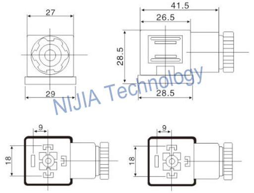
MPM Din43650A Pneumatic Fittings Junction Box Solenoid Coil ...
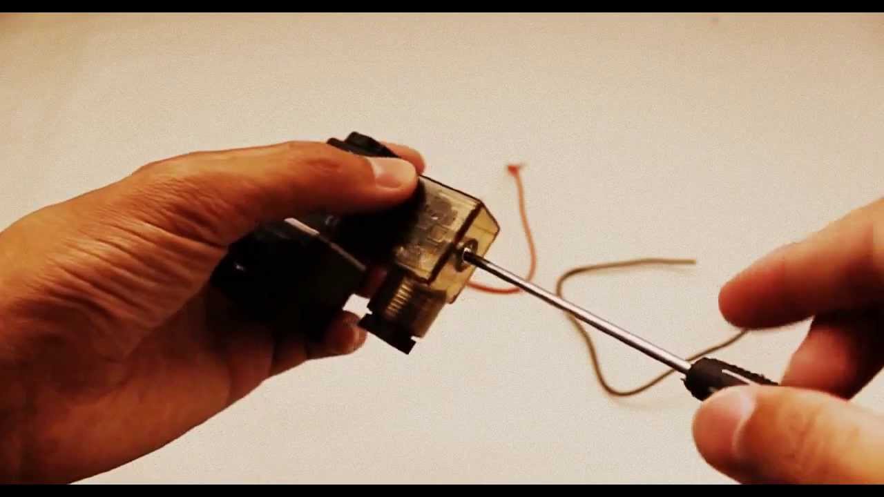
Solenoid Valve Electrical Connection Procedure

Types of Solenoids
Basic Hydraulic System - Components / Parts,Design & Circuit ...

Completing the Hydraulic Drawing | AutoCAD Electrical 2016 ...
Reading fluids circuit diagrams - hydraulic circuit examples

Relay-based Electro-hydraulic Systems – FLUIDSYS TRAINING CENTRE

Hydraulic Solenoid Selector/Diverter Valve, 13 GPM, 12v DC

Dump Trailer Double Acting Pump Wiring Diagram | Dump ...
Electro-Hydraulic Leveling

How To Wire A Electric Actuator Valve? | COVNA Actuator

How to Electrically Wire Up a 12 Volt DC Hydraulic Pump Power Pack Twin Solenoid Coils & Thermistor

Hydraulic Solenoid Valve - How They Work | Tameson.com

Solenoid Valve: What Is It? How It Works, Materials & Uses

How to Wire Hydraulic Power Pack,Power Unit Diagram Design
W600 Wiring: Solenoid Valves
Directional control valve


Comments
Post a Comment