41 miller 14 pin connector wiring diagram
PDF This manual covers equipment which is no OPERATING ... DC400 (codes with 14 pin amphenol) B. INDIRECT CONNECTION K963 6 P A K963 K864 14 P A K963 a K864 Aa. POWER SOURCE DC250 DC400 (older codes with termi-nal strip) K843 K963 Ta S K963 a K843 Aa. 1 * Disconnect ground lead at connector end of K963 when used with V250S. See CONNECTION OF THE AMPTROL TO THE POWER SOURCEin this manual for details. Inserting a pin in a 8 and 14 pin connector - YouTube Inserting a pin in a HD36-18-14SN-059 14 pin PLUG (attachment side) ASM LADD AUX
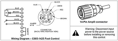
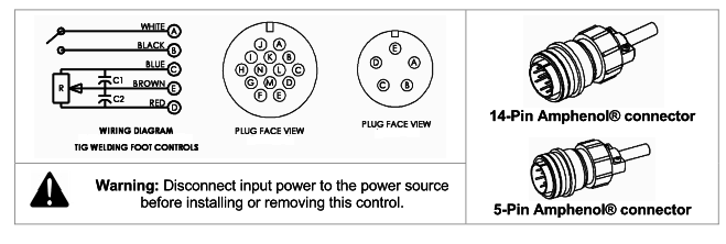
SSC Controls C810-1425 TIG Foot Pedal, Miller, 14-Pin Plug ... TIG welding foot control pedal for Miller welders using a 14-pin connector. Features heavy-duty formed steel construction, wide base for secure footing that won't tip over, precise current adjustment with continuous pot resolution, improved low-current welding with patented design, neoprene cable with highly flexible stranding for less breakage (26 x #34 tinned copper), and non-slip traction ...
Miller 14 pin connector wiring diagram
PDF OWNER'S MANUAL - Miller 2011 MILLER Electric Mfg. Co. FORM: OM-874D 093 324 MIC-4 Interface Control 2011−01 1. Safety Symbol Definitions ... lows remote controls with 14-pin plugs to connect to the 5-pin remote receptacle on MIC-4. ... Circuit Diagrams and Wiring Diagram 187 974 171 996-A D E C B A F PLG51 D C E B A RC51 X SIL Z PLG50 50 CR50 505 504 506 501 503 BLK ... Miller 14 Pin Connector Wiring Diagram - Wiring Site Resource 308 Miller 6 pin rotary amperage control cable length28 ft. Includes 25 76m cable and 14 pin connector. Replacement parts and wiring diagram. For miller and hobart tig welders. I was going to try to hook a 14 pin up to it as well. Heres a wiring diagram for a 14 pin rfcs 14 and 6 pin rfcs 6l foot contro. Miller 14 Pin Wiring Diagram - mungfali.com Miller 14 Pin Connector Wiring Diagram - Wiring Site Resource. Miller 14 Pin Connector Wiring Diagram - Ekerekizul. SSC Remote Foot Pedal for Miller TIG Welders - 14pin plug (RFCS-14) | eBay. TIG Foot Pedal Control - On/Off + Current Control 2 Pin + 3 Pin *FAST ...
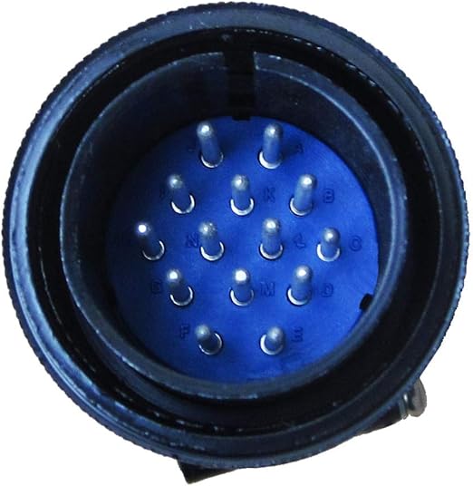
Miller 14 pin connector wiring diagram. Amazon.com: 14 pin connector 14 Pin Male Plug,Cable Mounted Male Plug, Industrial Cord Mounted Male Power Connector ,Remote Current Control And Remote Wire Feeder Functions,for Miller Welder 4.7 out of 5 stars 11 $17.72 $ 17 . 72 14 Pin Male Plug 136961 141162 Miller Hobart Wire Feeder ... 14 pin, metal, cord mounted male plug. This plug is equivalent to Miller p/n 136961 if you purchased a metal plug, or Miller's p/n 141162 if you purchased a plastic plug. This 14 pin connection is found on many Miller welders and is used for many different functions - remote amperage control and remote wire feeders are 2 of them. Tig Welder Foot Pedal Wiring Diagram my new tig job i am using a lincoln welder, i can't stand the foot pedal, is there anyway to convert a miller pedal? and there is a wiring diagram inside the foot pedal with the colours and codings of the wires lincoln miller 5 & 14 pin A C B E the wiring diagram conversion and . PDF Foot Controls RFCS-5, RFCS-5HD, RFCS-6M, RFCS-14 ... - Miller Miller Electric manufactures a full line of welders and welding related equipment. For information on other quality Miller products, contact your local Miller distributor to receive the latest full line catalog or individual specification sheets. To locate your nearest distributor or service agency call 1-800-4-A-Miller, or visit us at
14 pin connection - Miller Welding Discussion Forums Trouble with cable. So, In an effort to make my own 100 foot extension cord, for the WC24 and rhc-14 and 12 rc feeder, I ordered a male and female 14 pin plugs, and then searched high and low for the wire. All my sources for 16/8 were quoting me at least 3.00 a foot. The miller 75 foot cord is just 200.00. Miller 14 Pin Connector Wiring Diagram - Free Wiring Diagram CBB Miller 14 pin connector wiring diagram. Im looking for a pin or wiring diagram for the spoolmatic 3 which hooks up to the wc115 or the wc3 i belive 01 12 2012 1126 pm 4. Need to know on the 14 pin connector what color wire goes to what pin on a miller s 22p12 remote miller welding tools question. Miller 30a Spool Gun Wiring Diagram - schematron.org Miller 30a Spool Gun Wiring Diagram. Millermatic plus 30A Spoolgun (Canada) This the wiring diagram to convert the 30A 8 wires 10 pin connector plug to fit the MTSS. Spoolmatic 30A. Processes This Owner's Manual is designed to help you get the most out of your. Miller products. miller 14 pin info page - Weldmart Online MILLER STYLE 14 PIN RECEPTACLE DIAGRAM. HOW TO IDENTIFY THE 14 PIN CONNECTOR ON YOUR MACHINE. 1. With the machine turned on (the cooling fan may or may not run with the machine "on"). Normally of the machine has a pilot light that lights when the machine is "ON". 2. With a meter on AC Voltage check between pins A & B.
Older Miller TIG Pedal Conversion? - American Welding Society I think all you need to do is order the 14-pin connector from Miller or re-use an old one and connect the wires to the correct pins. If the wires are soldered to the pins in the old connector, you should be able to remove the soldered pins from the old connector, remove the correct pins on the 14-pin connector and push the pins in their correct locations. Wired Pushbutton Fingertip Control | MillerWelds Rocker 14 Pin 129337 Rotary East-West 14 Pin 151086 Push Button 2-Button 14 Pin 300666 14 pin connector - Miller Welding Discussion Forums 14 pin connector. 08-19-2010, 04:12 PM. I am trying to figure out what to use for a gas valve on my little miller inverter cst280. I have had it for about a year now, and I just emptied my third bottle of argon to atmosphere because I was stupid enough to forget to turn off the valve on the tig torch head... My question: is there an output on ... SG-KIT-DT-14-F - 14 Pin Female Kit - Deutsch - Attachment ... I am trying to add a blade attachment to my John Deere 320E. I bought the kit for the JD, but I need two connectors so I can attach the blade wiring.. I need a 14 pin round female and a 3 pin round male. Do you have a part number for the 3 pin. PLEASE CLICK HERE. Hello Do you have a wiring diagram for a female 14 wire plug on a cat broom?
Weld Control Selector Guide
Miller 14 Pin Connector Wiring Diagram - autocardesign Apr 24, 2020 · Miller 14 Pin Connector Wiring Diagram – wiring diagram is a simplified normal pictorial representation of an electrical circuit. It shows the components of the circuit as simplified shapes, and the capability and signal associates along with the devices.
Trailblazer remote wiring? - Miller Welding Discussion Forums
Miller 14 Pin Connector Wiring Diagram Bobcat 7 Pin ... Wiring Diagram April 24, 2020. Miller 14 Pin Connector Wiring Diagram Bobcat 7 Pin Diagram Wiring Diagram Page is one of the pictures that are related to the picture before in the collection gallery, uploaded by autocardesign.org. You can also look for some pictures that related to Wiring Diagram by scroll down to collection on below this picture.
WeldingWeb - Welding Community for pros and enthusiasts
homemade remote wiring On page 24 you can find the wiring diagram. The rheostat is R1 with wires 24 and 23 running to it. You just need to take one or the other (for this example I'll use 24) and run it to the middle terminal of a single pole dual throw switch.

Pin by Neletya Atan on Zvuk | Car audio systems, Truck audio ...
28 Miller 14 Pin Connector Wiring Diagram - Wiring Diagram ... 57M7390 - CONN TYCO CPC3 3W F BLK PLSTC fits John Deere ... Miller 14 Pin Connector Wiring Diagram - Wiring Site Resource. 1562031060 - Cap assembly, oil filter. Engine, cooler ... 28 Miller 14 Pin Connector Wiring Diagram - Wiring Diagram List. Connectors and Cables.

Build a 240V Power Adapter for Your MIG Welder - Make:
Male Plug Connector Wiring Diagram - Wiring Sample Rj45 Connectors Openclipart. Wiring a phono plug. Miller 14 pin info page weldmart online miller style 14 pin receptacle diagram how to identify the 14 pin connector on your machine 1 with the machine turned on the cooling fan may or may not. 220 4 Prong Plug Wiring Diagram Source.
S-74S, S-74D
Best Of Miller 14 Pin Connector Wiring Diagram | Wiring ... Best Of Miller 14 Pin Connector Wiring Diagram -Allowed to be able to my website, on this period I'm going to explain to you regarding miller 14 pin connector wiring diagramAnd today, this can be the very first graphic: Miller 14 Pin Connector Wiring Diagram 2018 Wiring Diagram for 220 from miller 14 pin connector wiring diagram , source:shahsramblings.com
Miller XMT® 350 CC/CV, Dinse, Aux Power
42 skid steer 14 pin wiring diagram - diagram I have a Cat 272D2 xhp skid steer with a Cat 6 way dozer blade, I accidentally caught the wire harness and pulled the 5 wires out of the 14 pin plug, I cant find a wiring diagram to match up wire A207 … read more 14 PIN 7ft "Extreme Duty" Connector Harness.

Miller Foot Pedal Fix RFCS 14 HD
Miller 14 Pin Wiring Diagram - mungfali.com Miller 14 Pin Connector Wiring Diagram - Wiring Site Resource. Miller 14 Pin Connector Wiring Diagram - Ekerekizul. SSC Remote Foot Pedal for Miller TIG Welders - 14pin plug (RFCS-14) | eBay. TIG Foot Pedal Control - On/Off + Current Control 2 Pin + 3 Pin *FAST ...

6. 14-pin plug information | Miller Electric XR Control User ...
Miller 14 Pin Connector Wiring Diagram - Wiring Site Resource 308 Miller 6 pin rotary amperage control cable length28 ft. Includes 25 76m cable and 14 pin connector. Replacement parts and wiring diagram. For miller and hobart tig welders. I was going to try to hook a 14 pin up to it as well. Heres a wiring diagram for a 14 pin rfcs 14 and 6 pin rfcs 6l foot contro.
miller tig 14pin control pinout - Miller Welding Discussion ...
PDF OWNER'S MANUAL - Miller 2011 MILLER Electric Mfg. Co. FORM: OM-874D 093 324 MIC-4 Interface Control 2011−01 1. Safety Symbol Definitions ... lows remote controls with 14-pin plugs to connect to the 5-pin remote receptacle on MIC-4. ... Circuit Diagrams and Wiring Diagram 187 974 171 996-A D E C B A F PLG51 D C E B A RC51 X SIL Z PLG50 50 CR50 505 504 506 501 503 BLK ...

VersaMed iVent 201 Interface Board Replacement - iFixit ...
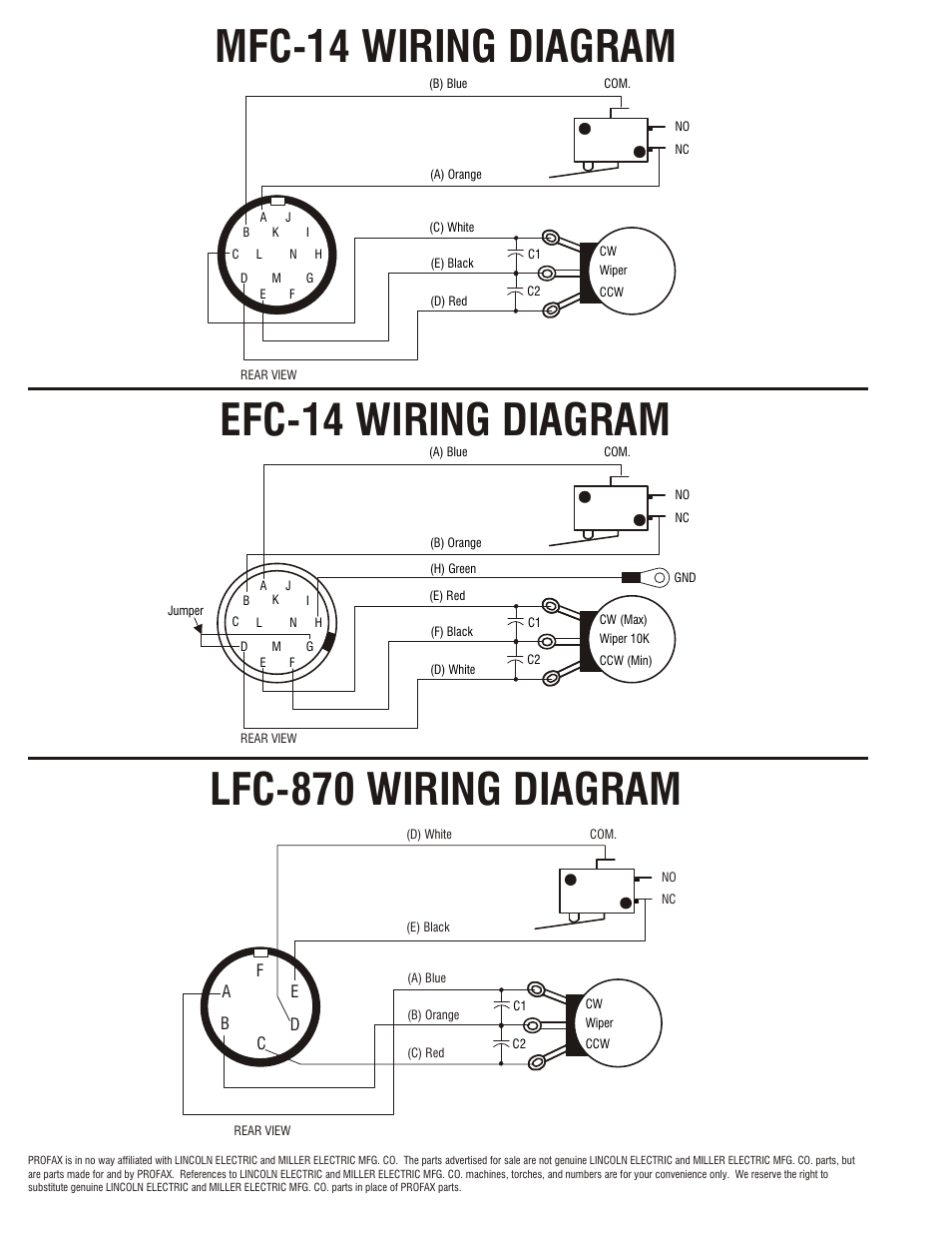
Efc-14 wiring diagram | Profax EFC-14 User Manual | Page 4 / 4

Practical Machinist - Largest Manufacturing Technology Forum ...
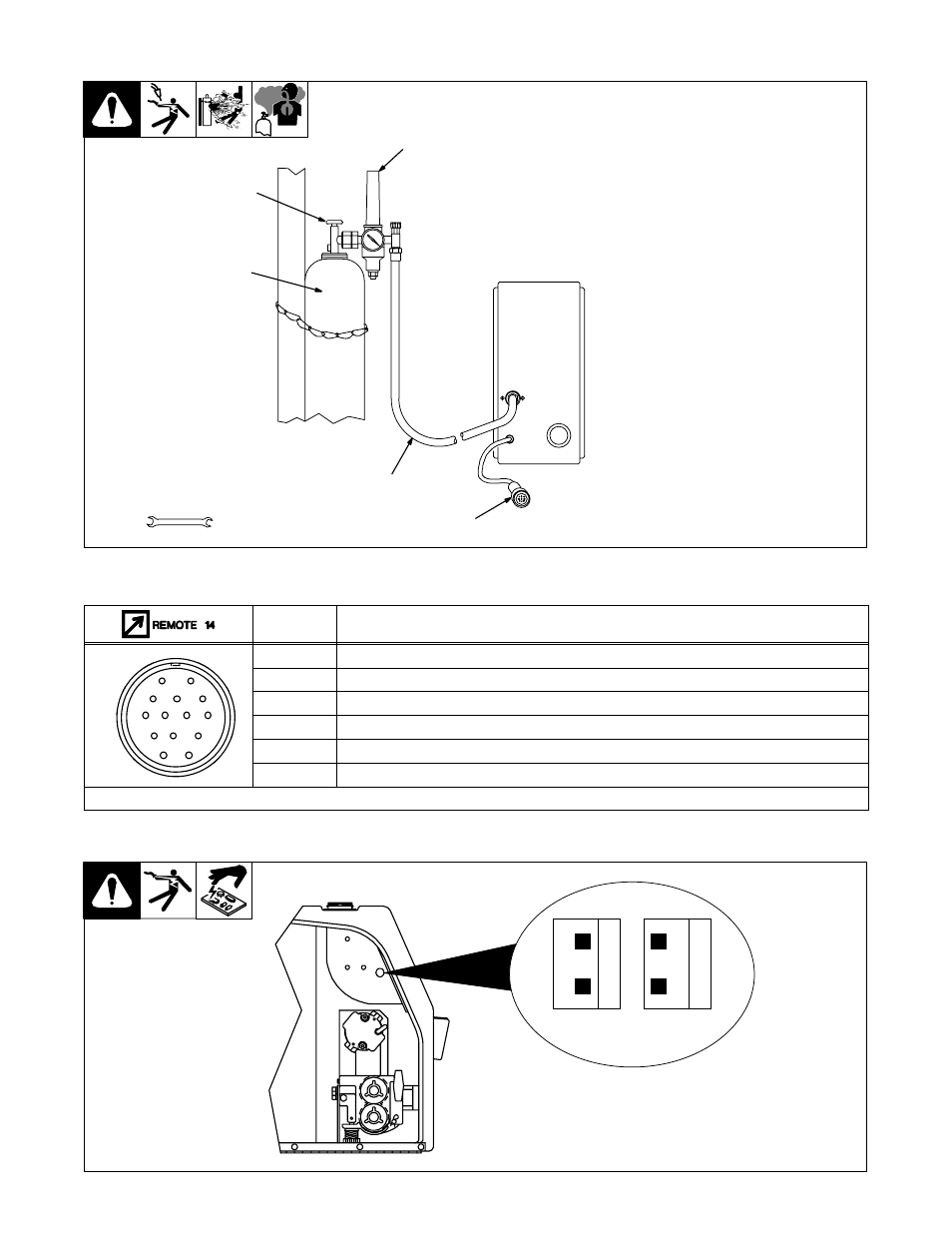
4. connecting shielding gas and 14-pin plug, 5. 14-pin plug ...

HellermannTyton LWL-Spleißmuffen (Durchgangs-/Verteilmuffen ...

credentiality: Teardown: Miller RFCS RJ45 tig welding foot pedal
Older Miller TIG Pedal Conversion?
SSC Fernbedienung für Lorch TIG Schweißgeräte – 14pin Plug ...
Miller Spoolmatic 30a - Shop Floor Talk
FW-M23KU17O-G-CP-ME-SH-14.5 Round connector M23 x 1 – Field ...
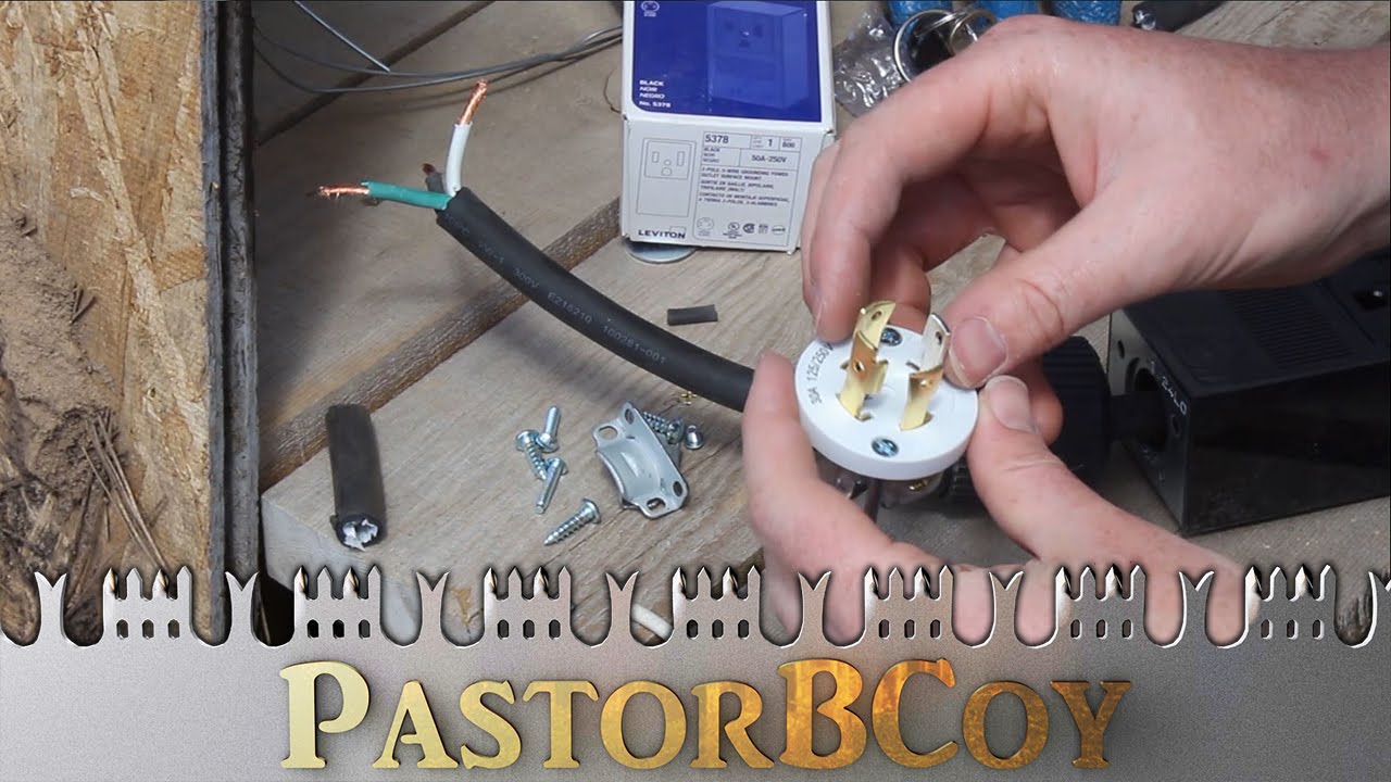
Wiring a Conversion Plug from Generator to Welder

Miller XMT 300 CC/TIG User manual | Manualzz
14 Pin Male Plug 136961 141162 Miller Hobart Wire Feeder ...
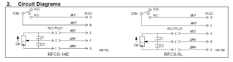
THE SSC CONTROLS COMPANY

SSC Remote Foot Pedal for Miller TIG Welders - 14pin Plug ...

SSC Foot Pedal for Lorch TIG Welders - 14pin plug - FR-35

Kaufen Sie Taktische Taschenlampe Airsoft Ein Peq15 ...
14 pin help for tig switch and solenoid wiring - Miller ...
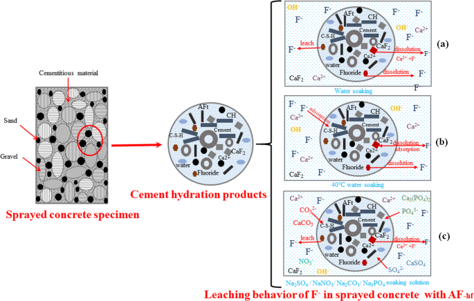
Leaching behavior and environmental safety evaluation of ...
miller 14 pin info page

10+ Panasonic Car Radio Wiring Diagram | Panasonic car audio ...
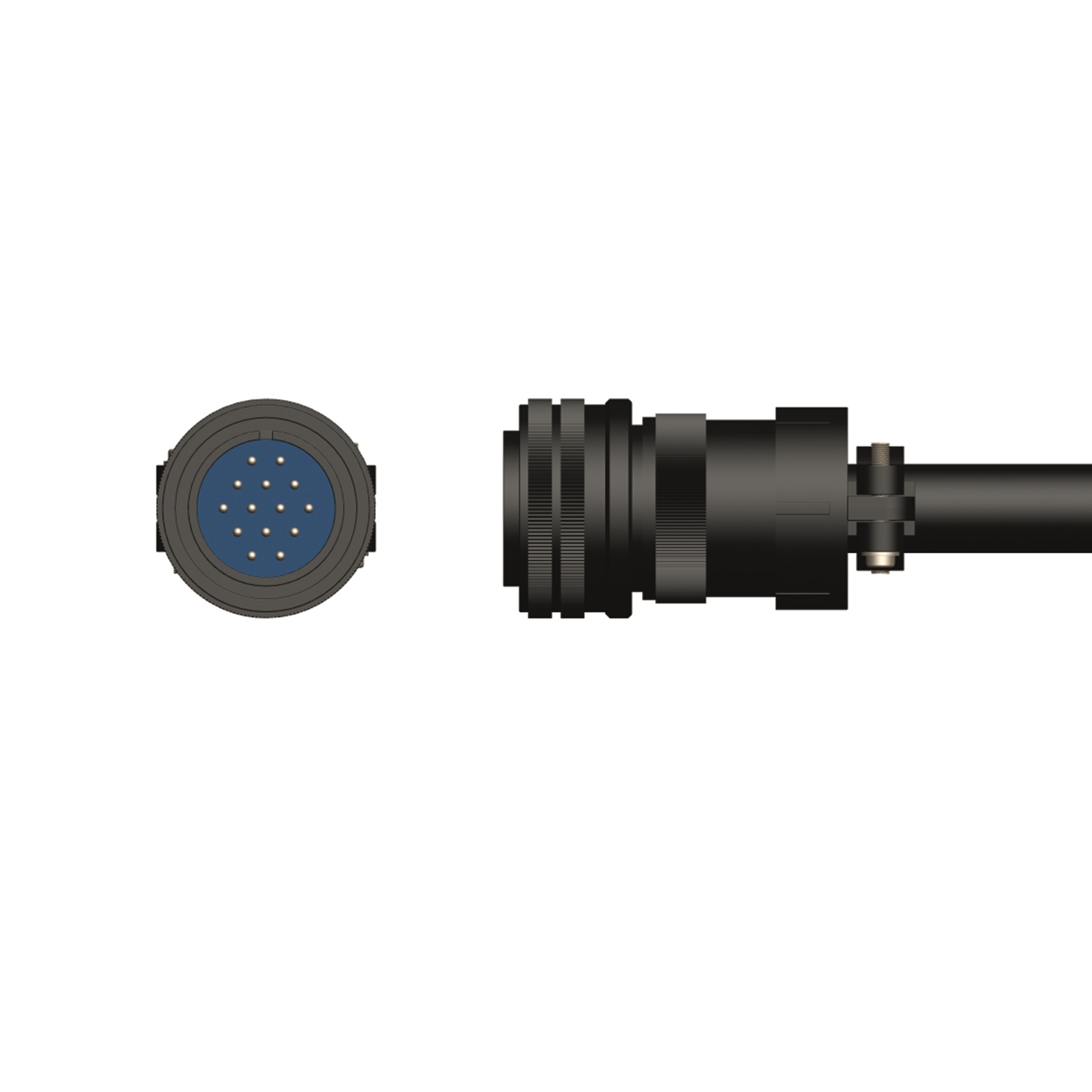
Miller® 14 Pin Amphenol Plug
SSC R810-0525 Automation Control R810-1425 Replaces Miller 242211020

Miller 6-Pin To 14-Pin Remote Control Adapter Cord 300507

SG-BPH-14-6-9DP/DT - 14 Pin Female to Delphi 2 Pin Harness ...

Miller PROCESS SELECTOR CONTROL User manual | Manualzz

Miller SuitCase 12RC with Bernard Q300 Gun, Meters, Remote ...

SSC Controls 14 Pin Male Plug for Miller Welders p/n 141162 ...
THE SSC CONTROLS COMPANY
Foot pedal adapter - Miller Welding Discussion Forums

Bedienungsanleitung Klarstein Studio 1 - 10030845 (Seite 13 ...


Comments
Post a Comment