39 nitrous wiring diagram
Wiring Diagrams - Nitrous Outlet These Wiring Diagrams will help you wire up your Nitrous System or Nitrous Accessory. Includes Nitrous Purge, Nitrous Bottle Heater, and Dedicated Fuel System. Your #1 Source for everything Nitrous. Dealer Locator Account. Toggle navigation 254-848-4300 Speak with a Nitrous Expert M-F 8:30am - 5:30pm CST Call or Text Today! ... Nitrous Express Wiring Diagram - schematron.org Wiring Diagrams. Nitrous Wiring Harness - This harness is specific for LS1 engines with a 4L60e Transmission and a Drive By Cable Throttle Body. This harness is Plug and Play with the engine and transmission, and only requires a 4 wire hook up to fire up the engine!
PDF Universal Wet 4, 6 & 8 Cylinder Nitrous Oxide System Chapter 1 Introduction to your CFNS Nitrous Oxide Kit 1.1 General Information This Kit is intended for 4, 6, & 8 cylinder applications. This kit was designed to be used on late model multi-point fuel injection type engines with 43 psi ± 5 psi fuel pressure. This nitrous oxide system injects a mixture of nitrous oxide and fuel into the air ...

Nitrous wiring diagram
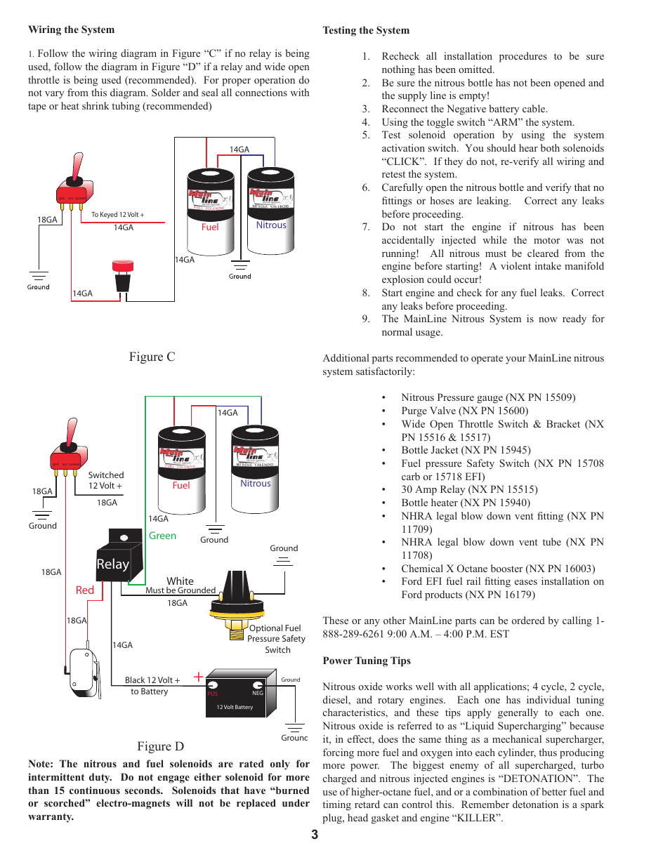
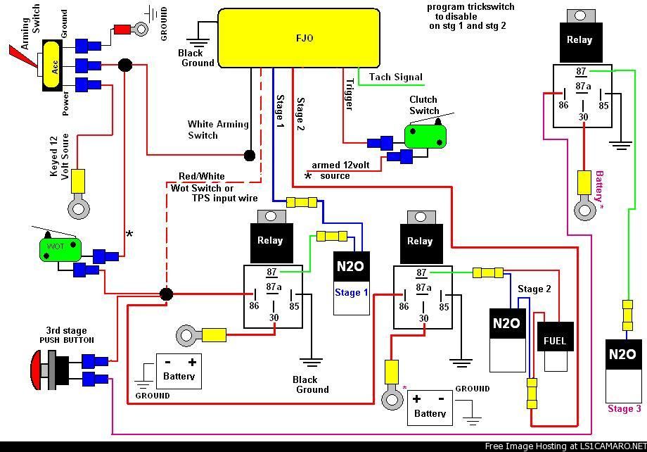
PDF Two Stage Nitrous Wiring Diagram two-stage-nitrous-wiring-diagram 1/1 Downloaded from stats.ijm.org on April 7, 2022 by guest Two Stage Nitrous Wiring Diagram When people should go to the books stores, search creation by shop, shelf by shelf, it is really problematic. Nitrous Wiring Diagram With Transbrake Nitrous Wiring Diagram With Transbrake The stud labeled "2" is for the transbrake. It is activated by applying +12volts. If you have any questions, email daver@wiringall.com or call When wired in series with your nitrous system relay it will enable you plished by splicing into the trans brake solenoid wiring and using this power source to. PDF Read all Instructions before beginning!!!! - Nitrous Express Follow the wiring diagram below that matches the system you have. For proper operation do not vary from this diagram. Solder and seal all connections with tape or heat shrink tubing (recommended) Testing the System 1. Re-check all installation procedures to be sure nothing has been omitted. 2.
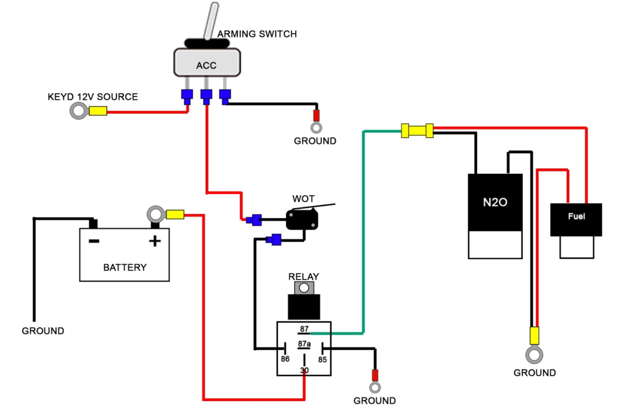
Nitrous wiring diagram. OWNER'S MANUAL - Holley Figure 9 General Electric Wiring Diagram. 2.7 Testing for Proper Operation without Nitrous Bottle Hook Up. 1. Connect the battery and prime the fuel system ...22 pages Read all Instructions before beginning!!!! - Nitrous Express Connect all wires per NX Self- Programming Throttle Position Activation Switch wiring diagram using a. 1 to 3 amp fuse in series with the red wire. 5. On ... PDF WIRING DIAGRAM FOR N2O WITH TRANSBRAKE ... - Nitrous Supply WIRING DIAGRAM FOR N 2O WITH TRANSBRAKE NOS P/N 15838 NOS P/N 15618 NOTES: 1) Bottom view of all relays 2) All relays must be diode suppressed N4~N 2O N4~N 2O N/C N/O COM TRIG GND 12 Volt from Transbrake Battery Ground 87 87A 30 86 85 Fused and Switched 12 Volts lts Micro Switch Arming Switch Instructions - Induction Solutions WIRING DIAGRAMS. Single Stage Wiring ... Digi-set Instructions. Wiring with and without a Progressive Controller (Transbrake) Wiring with and without a Progressive Controller ... Tyco 75 Amp Relay Schematic. NOS Launcher Wiring. INSTRUCTIONS. Nitrous Solenoid Plunger Info. Boogie Box (NPC-1006) User Manual. NPC-2006 User Manual. NMS-1000 User ...
Nitrous Tachometer Wiring Diagram - schematron.org THROTTLE & RPM-ACTIVATED NITROUS CONTROL SYSTEM P/N NOS Installation Instructions ASNOS wiring diagram from your original instructions. Use only the diagram shown in this instruction booklet. use the TACH terminal. 4. Connect the yellow wire to the ground side of the activation circuit of your NOS relay. Be sure that the. Wiring Diagrams - FuelTech USA Wiring Diagrams FT450 Honda K20-24Version: 1.0 | Size: 0.92 MB FT550 8 Cyl Smart CoilVersion: 1.0 | Size: 0.52 MB FT550 6 Cyl Smart CoilVersion: 1.0 | Size: 0.51 MB ... Megasquirt Support Forum (MSEXTRA) Nitrous wiring scheme. All Megasquirt 1 support questions. See also the ... 2005 6:28 pm. Nitrous wiring scheme. Post by Jon k » Mon Sep 03, 2007 6:09 am. Here is how my NX kit says to wire the kit... Now, if I want to control this setup with MegaSquirt, where do I wire in? ... the MS2 manual says that the arm is a ground, but in the image ... Wiring diagrams for 2 stage nitrous kit 2 stage nitrous diagram Can you consider leaving the first 100 hp stage on and have the second stage add an additional 100 hit on the button. TT = 200 Hp. Most multi stage systems function this way. Are you activating any ignition retards with this system? Let me know how you prefer the system to function and I will provide you the diagram.
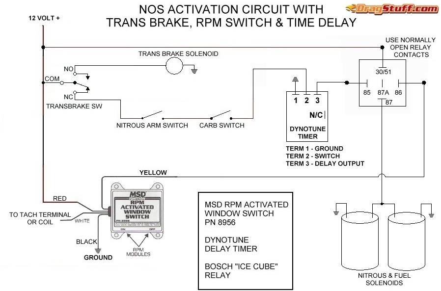
Nitrous System Wiring Diagrams - Dragstuff Nitrous Wiring Diagrams Nitrous Wiring Diagrams by John Heard Last Updated Jan 4, 2015 Single Stage NOS System with Transbrake Interrupt Relay. Single Stage NOS System with Transbrake Interrupt Relay, MSD Window Switch, and Dynotune Delay Timer. Nitrous Express Proton Kit Wiring Diagram wiring diagram in Illustration D) (For systems with the TPS auto-learn switch skip to #7 Additional parts recommended for operating your PROTON nitrous system satisfactorily: . A tune up from any other brand of nitrous kit will not work. be controlled by the ignition switch (See Wiring Schematic for Progressive Controller). 3. PDF Controller Requires the Use of Output Drivers to Power the ... AMS-2000 Nitrous Controller Wiring Guide Page 5 Holley Driver Part# 554-111 Holley 554-111 High Current So l i d St at e Drivers are recommended to handle the hi gh current l oads f or ni t rous and fuel solenoids on this system. T he AMS-2000 cont rol l er has a 7 amp maximum output current capacit y and t he Hol l ey sol i d st at e ... Nitrous Oxide Instructions Learn how to install your Nitrous kit, Bottle Heater, Purge kit etc. You will also find wiring diagrams. coming soon, we will have awesome step by step color photo install instructions outlining almost every single step from taking your kit out of the box to putting on the finishing touches with easy to understand pictures.
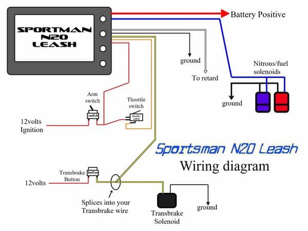
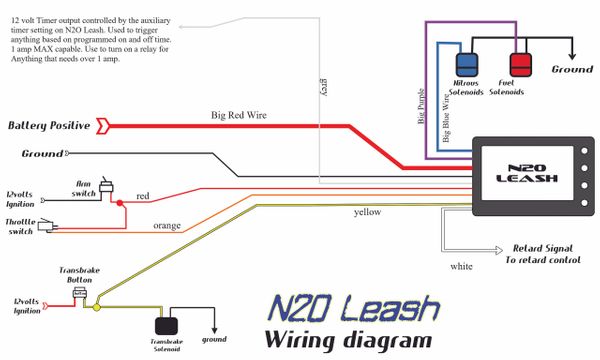
Nitrous Wiring Diagram With Transbrake - schematron.org Trans Brake 12 Volt Solenoids Solenoid Battery Ground Battery Ground WIRING DIAGRAM FOR N 2O WITH TRANSBRAKE NOS P/N NOS P/N NOTES: 1) Bottom view of all relays 2) All relays must be diode suppressed N4~N 2O N4~N 2O N/C N/O COM TRIG GND 12 Volt from Transbrake. Induction Solutions Tech Sheet. CATALOGS.
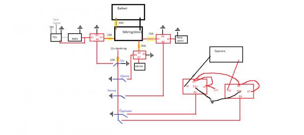
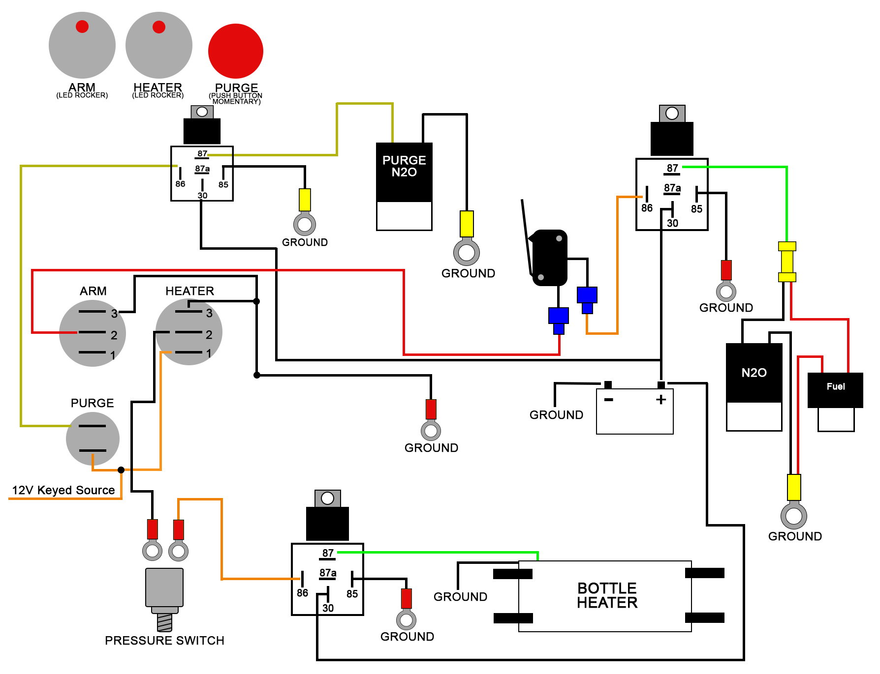
PDF FOUR BUTTON SWITCH PANEL WIRING DIAGRAM - Nitrous Outlet nitrous outlet project: opener wiring diagram filename: opener wiring diagram.ai created date: 08/14/2020 pages: contact information: 2 of 2 rev #: 02 opener arm heater opener purge 87 87a 86 30 85 87 87a 86 30 85 opener relay 1 open close opener relay 2 opener 1 ground battery anel 3 2 2 1 10 amp fuse jumper 10 12 ga 12 ga 10 ga 16 ga 16 ga 16 ...
Nitrous And Transbrake Wiring Diagram Wiring your nitrous kit has NEVER been so easy! connect you 12volt power from your throttle switch or manual nitrous button, connect you transbrake or clutch 12volt signal for nitrous safety so that Check out the wiring diagram in the pics. The stud labeled "2" is for the transbrake. It is activated by applying +12volts.
Nitrous Wiring Diagram - Holley Nitrous Wiring Diagram; If this is your first visit, be sure to check out the FAQ by clicking the link above. You may have to register before you can post: click the register link above to proceed. To start viewing messages, select the forum that you want to visit from the selection below. ...
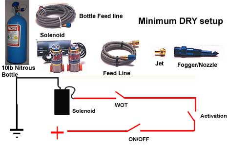
Wet Kit Electrical Drawing Without Relay - Nitrous oxide Snowmobile nitrous kits are the best way to make big power! More affordable than boondockers or bossnoss. Nitrous Oxide Kits Systems and components are the quickest and easiest way to get large horsepower increases with a minimum of engine modifications and expense. Nitrous Kits offer serious horsepower at the flip of a switch.
PDF Universal Single Stage Wiring Diagram 2020 - Nitrous Outlet nitrous outlet — universal single stage wiring diagram company / contact: nitrous outlet | 305 south 28th street | waco, tx 76634 | 254.848.4300 | customerservice@nitrousoutlet.com | this document and the designs or information contained within are the sole property of nitrous outlet and
PDF Caution - Nitrous Express Wiring diagram for MSD RPM Switch Limited Warranty: Nitrous Express (the warrantor) hereby warrants its product to the original purchaser thereof (the consumer) against any and all defects in workmanship and material under the following terms and conditions: The Limited Warranty is specifically limited to the original
Nitrous Wiring - Holley Hello. I'm wiring up a Nitrous Express kit and it comes with a micro switch/WOT switch. However, I'd like to control it completely through the ECU. I have my parameters setup in the Nitrous ICF. I understand that I need Holley 554-111 for progressive control, but will that also be the only wiring needed for the ECU to communicate with the nitrous solenoids?
PDF Read all Instructions before beginning!!!! - Nitrous Express 2. Following the wiring diagram, route all wires but make no connections. 3. You must determine which wire on your vehicle's TPS is the output signal to the vehicles computer. Refer to your vehicle's service manual to determine which is the output wire. Connect all the wires as shown in the diagram.
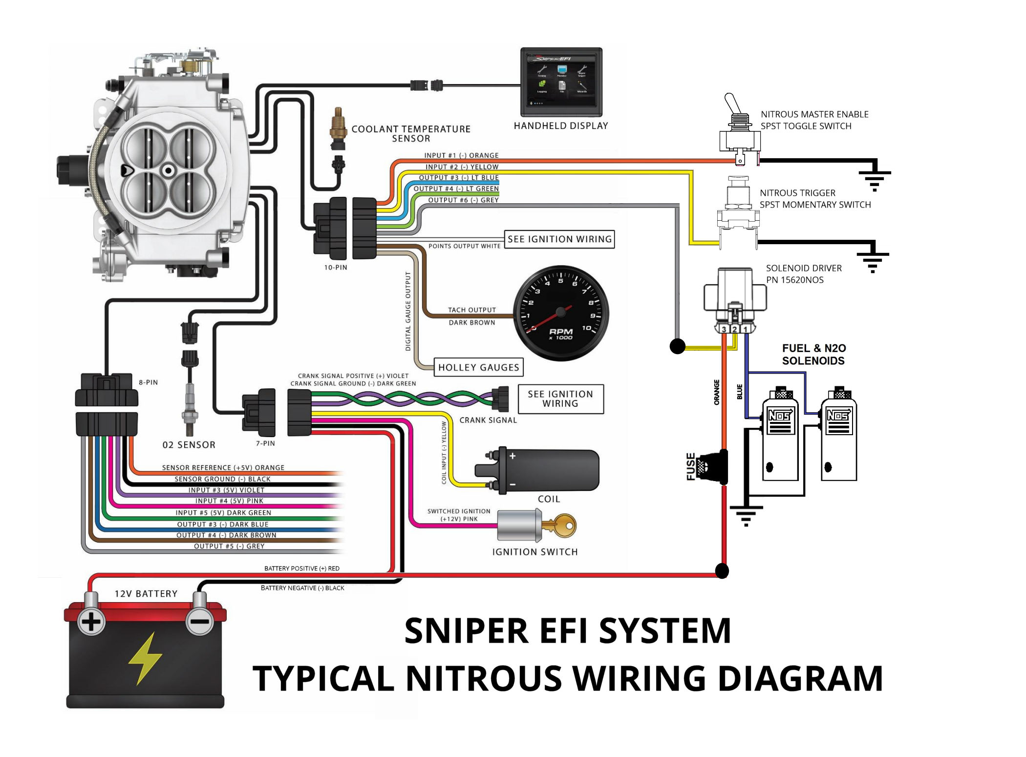
Holley Sniper Wiring Diagram This manual contains information and diagrams related to wiring most Holley EFI products including ECU's, ignition systems, nitrous systems, water/methanol injection systems, sensors, and more. 3 Important Wiring "Do's and Don'ts. Demystifying Holley Terminator and Sniper Ignition Hookup. Here is a wiring diagram showing the ...
time-based progressive nitrous controller installation instructions Figure 9 Wiring Diagram (Wet Manifold Systems—Two Nitrous & Two Fuel Solenoids)..…… 13. Figure 10 Tuning Map—Solenoid Duty Cycle (Power) versus Time…16 pages
Digi Set Nitrous Wiring Diagram Snowmobile nitrous kits are the best way to make big power! More affordable than boondockers or bossnoss. Nitrous Oxide Kits Systems and components are the quickest and easiest way to get large horsepower increases with a minimum of engine modifications and expense. Nitrous Kits offer serious horsepower at the flip of a switch.
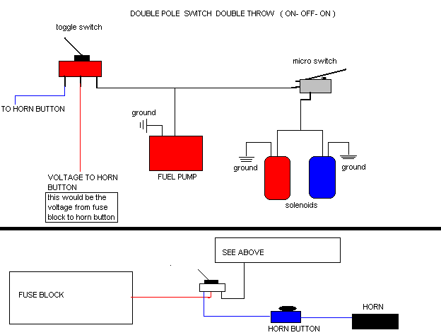
Motorcycle Nitrous Horn Wiring Diagram Snowmobile nitrous kits are the best way to make big power! More affordable than boondockers or bossnoss. Nitrous Oxide Kits Systems and components are the quickest and easiest way to get large horsepower increases with a minimum of engine modifications and expense. Nitrous Kits offer serious horsepower at the flip of a switch.
PDF Stand Alone Purge Wiring Diagram 2020 - Nitrous Outlet nitrous outlet — stand alone purge system wiring diagram company / contact: nitrous outlet | 305 south 28th street | waco, tx 76634 | 254.848.4300 | customerservice@nitrousoutlet.com | this document and the designs or information contained within are the sole property of nitrous outlet and
PDF Read all Instructions before beginning!!!! - Nitrous Express Follow the wiring diagram below that matches the system you have. For proper operation do not vary from this diagram. Solder and seal all connections with tape or heat shrink tubing (recommended) Testing the System 1. Re-check all installation procedures to be sure nothing has been omitted. 2.
Nitrous Wiring Diagram With Transbrake Nitrous Wiring Diagram With Transbrake The stud labeled "2" is for the transbrake. It is activated by applying +12volts. If you have any questions, email daver@wiringall.com or call When wired in series with your nitrous system relay it will enable you plished by splicing into the trans brake solenoid wiring and using this power source to.
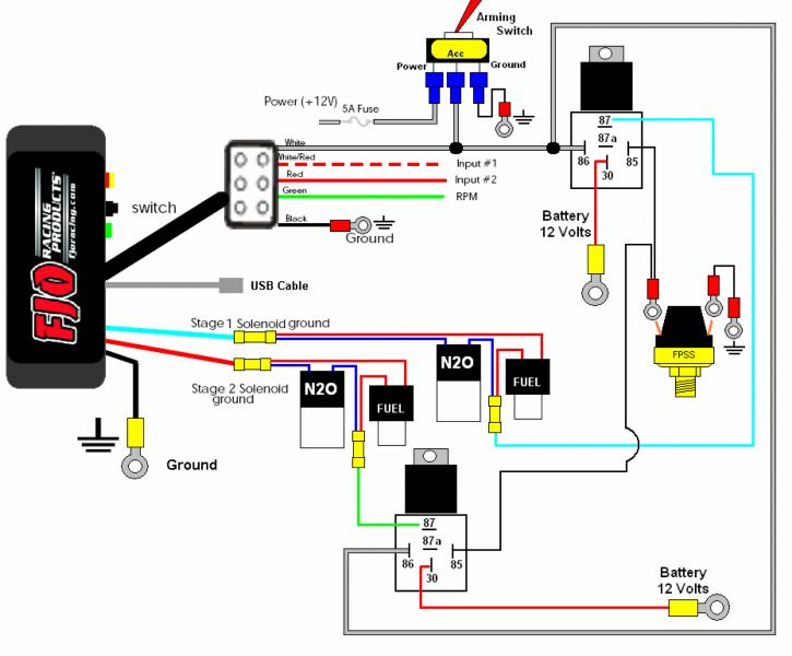
PDF Two Stage Nitrous Wiring Diagram two-stage-nitrous-wiring-diagram 1/1 Downloaded from stats.ijm.org on April 7, 2022 by guest Two Stage Nitrous Wiring Diagram When people should go to the books stores, search creation by shop, shelf by shelf, it is really problematic.






Comments
Post a Comment