39 septic pump float switch wiring diagram
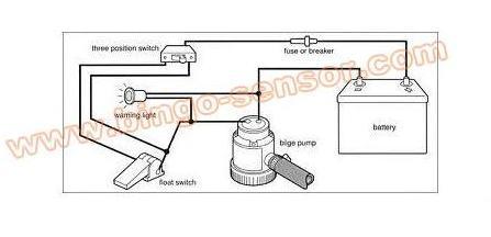
How To Hard Wire A Float Switch To A Submersible Pump Once these connections are made, you are ready to turn the power back on and the submersible pump should operate according to the position of the float switch. Below is a diagram of what is described in the paragraph above. If you have any further questions, call 1-877-925-5132. Float Switch Installation Wiring & Control Diagrams | APG Single Float Switch Wiring Control Schematic 2 Enlarge Image Control Schematic 1 Enlarge Image Let's start with the most basic float switch: a two-wire, single-pole, single-throw float switch. The rising action of the float can either close (i.e., turn on) a "Normally Open" circuit, or it can open (turn off) a "Normally Closed" circuit.
Septic Pump Float Switch Wiring Diagram Gallery - Wiring ... A wiring diagram is an easy visual representation of the physical connections and physical layout associated with an electrical system or circuit. It shows what sort of electrical wires are interconnected and may also show where fixtures and components may be connected to the system. When and How to Use a Wiring Diagram
Septic pump float switch wiring diagram
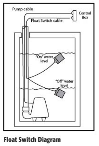
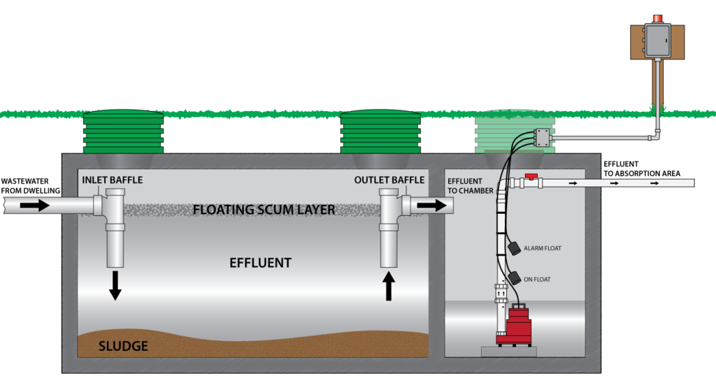
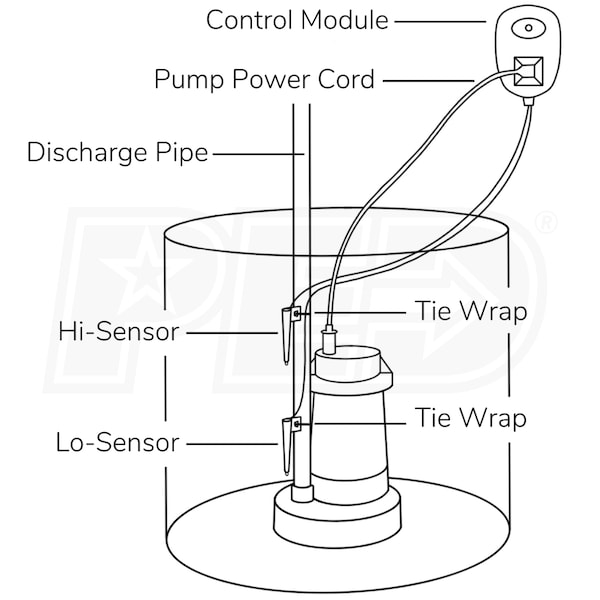
Septic Tank Float Switch: Functions, Types & Problems Types Of Septic Tank Float Switches. There are options when it comes to choosing a more appropriate septic tank float switch for your use. Some of the main variants include submersible sensors, pump duty floats, mechanical sump switches, control duty floats, and horizontal float switches. PDF Float Switch Package Instructions - Sump Alarm The above diagrams demonstrate a float switch utilizing the counterweight included in the package. A counterweight may not be necessary in your particular installation. In submersible pump applications, a float switch can be mounted as shown at left using only a wire tie. The Tether Length illustrated in the Figure can be Septic pump float switch | Electrician Talk If it has two floats, it has a relay in it. white is neutral black is hot and red is switch wire. when the tank fills with water both floats tip up, the short float switches the power to the red wire which starts the pump. when the water level drops the pump turns off when the the long float tips down. The Bitterness of Poor Quality Remains.
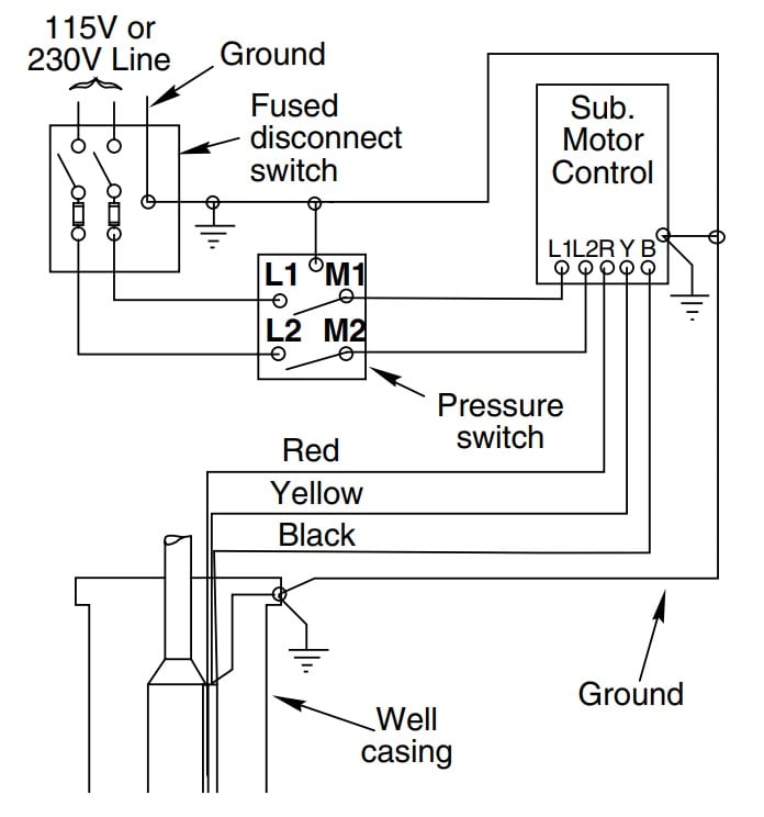
Septic pump float switch wiring diagram. Septic Pump Alarm Wiring Diagram - Wiring Diagram and ... Well Septic Systems Diagnostics Monticello Pump Services Sim A Three Phase Simplex Pump Control Panel See Water Inc Float Switch Installation Wiring Control Diagrams Apg Spi Bio Pump Control Panel With High Water Alarm Model 50b010 Whap Tg Wastewater Zoeller Pump Company Apak Alarm Systems Wiring a Receptacle for a Lift Pump for a Septic System How a Float Switch Works A float is basically is a switch, where the power comes in one wire, goes through a pair of contacts, and then travels back out through another wire. When the switch is open, which is the same as being off, this condition creates one example of an open hot. How To Wire a Septic Tank Pump & Alarm System - YouTube Enclosure Box I Used: Alarm with Float: Septic Pump: with Light and... 220 wiring/ float switch setup for septic effluent pump ... A simple sump pump with a linear rod simply clicks on and off with 2 different stops on the rod. In the case you are describing, the upper float might just be an alarm float, and the off/on differential is done with the bottom float. Who knows if your friend installed his correctly, or if it was modified after the fact.
Sump Pump Float Switch Adjustment | In-depth Guide Let's learn how to install the septic tank pump float switch first and then we'll learn about the problems you can encounter! To install the septic tank pump float switch, you must get your hands on the swing length and the float switch height first. Once you get it, you need to get the float switch's wire inside. Aerobic Septic System Wiring Diagram - schematron.org Aerobic Septic System Wiring Diagram - This is a image galleries about Septic Tank Float Switch Wiring schematron.org can also find other images like wiring diagram, parts diagram, replacement parts, electrical diagram, repair manuals, engine diagram, engine scheme, wiring harness, fuse box, vacuum diagram, timing belt, timing chain, brakes. Septic Tank Float Switch Wiring Diagram - schematron.org Septic system installers install the alarm float switch to the inside of the septic tank. The wiring of the float switch to the alarm circuit remains the homeowner's. The float switch moves with the water level in the tank and this determines when the pump turns on Please note: The information below refers to V pumps and wiring. How Do Float Switches Work (Diagram & Working Principle) Water Level Control's NEW Float switches work by using probes (instead of floats) to detect or (sense) water levels in a storage tank (water, oil, gas, etc). The sensor probes actually act as their own sensors and do not pass electricity through the probes which keeps them from fouling, degrading and deteriorating.
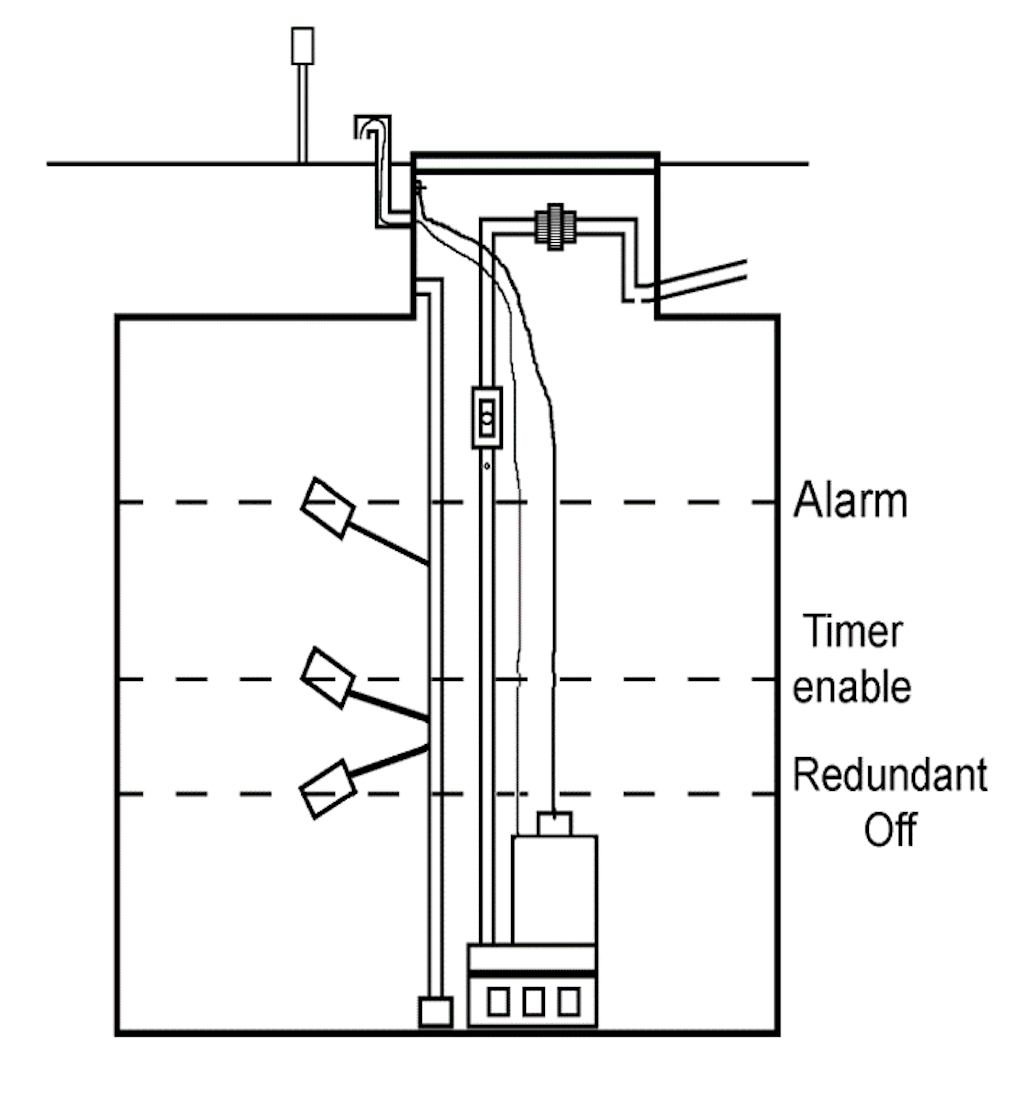
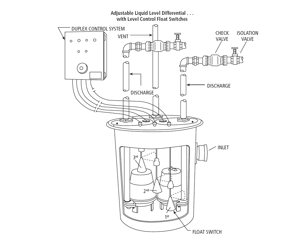
PDF Instructions Float Switch Settings and Adustments Float Switch Settings and Adustments Float Switch Settings and Adustments 1 Panel schematics and wiring diagram (residential panel shown) Two-Pump (Duplex) Systems, Timed-Dose, cont. 5 Redundant Off/Low-Level Alarm (in four-switch systems): 2½ inches (64 mm) below the switch above it. PDF Septic Tank Float Switch Wiring Diagram Septic Tank Float Switch Wiring Diagram 3hp control box for deep well pump compatible replacement. water terms glossary sta rite. antique allis chalmers tractor ac 160 tractorshed com. how to replace a broken air conditioner condensate pump. water pump repairs how to diagnose amp repair lost well. zoeller fm2102 owner s manual pdf download ... PDF Installation Manual Pump Packages - The Septic Store Step 5: Install Float Switch Assembly Table 1 provides float switch functions, positions, and marker tag colors for typical demand-dose (Y,G; Y,G,W; Y,B,R; or Y,B,R,W) and timed-dose (YG,R; YG,R,W) float switch configurations . 4a 4b 4e Valve Grommet 4 Stem (field-cut to length) Male adapter (connects to pump discharge) PVC flex hose Discharge ... Septic Pump Float Switch Wiring Diagram - Free Wiring Diagram Septic Pump Float Switch Wiring Diagram Assortment of septic pump float switch wiring diagram. A wiring diagram is a streamlined conventional photographic depiction of an electrical circuit. It shows the parts of the circuit as simplified forms, and also the power and also signal links between the devices.
Classic Whaler: Boston Whaler: Reference: Bilge Pump
Installation Instructions - SJE Rhombus Control Products Tank Alert® EZ Terminal Block Wiring Tank Alert® EZ DUO Tank Alert® XT Tank Alert® XT Terminal Block Wiring Tank Alert® XT Auxiliary Contacts Option Tank Alert® 4X Tank Alert® Solar Tank Alert® Solar Circuit Board-Battery Replacement. Level Monitoring. C-Con™ Converter Box SJE Level Monitor™ CL. Pump Switches. Pump Switch ...

Using DPDT Cross-Wired Alternating Relays with HIGH-LOW Float ...
Float Switch Wiring Diagram - justussocializing.org Float Switch Wiring Diagram - One of the most hard automotive fix tasks that a mechanic or fix shop can take is the wiring, or rewiring of a car's electrical system.The burden in reality is that every car is different. later irritating to remove, replace or repair the wiring in an automobile, having an accurate and detailed Float Switch Wiring Diagram is necessary to the skill of the ...

Using DPDT Cross-Wired Alternating Relays with HIGH-LOW Float ...
Septic Float Switch Wiring Diagram - justussocializing.org Septic Pump Wiring Diagram The best other is always to use a verified and accurate Septic Float Switch Wiring Diagramthat's provided from a trusted source. A good, traditional company that has a long track scrap book of providing the most up-to-date wiring diagrams approachable is not hard to find.

Aerobic System Control Panels, Aerobic System Control Box ...
Septic pump installation guide - InspectAPedia Make sure that the pump basin or well is large enough in diameter to give free movement to the float assembly without binding Don't lift the pump by its power cord Electrical circuit splices in damp or wet area need to be in waterproof junction boxes Install a battery-backup pumping system if your building is subject to power outages

Float Switch Cable Float Switch Oil Water Level Switch ...
How to Troubleshoot Septic Float Switches - Hunker If your septic system uses a pump to remove wastewater from the tank to a drain field, your system will include a septic tank alarm and float switch. When the float rises to an unacceptable level, it sets off an alarm to warn you that your tank may be about to overflow. At times the float switch will malfunction and sound the alarm when the ...
Adding Storage Tank To System? | Terry Love Plumbing Advice ...
Dual Float Switch Wiring Diagram - Wiring Schemas Dual float switch wiring diagram. Hold the float switch to the discharge pipe so the cage is below the bracket. These simple visual representations all. Up to 250 °c oodensity: Septic pump float switch wiring diagram download. A switch is an electrical component that can " make " or " break " an electrical circuit.
Bilge Pump Float Switch | Float Switch |Level Switch---BINGO ...
Step-by-Step Float Switch Wiring Instructions | APG Once you have figured out your switch points, use a clip or a mounting bracket to secure the cable above the well or tank, with the bottom of the float hanging at the exact position needed (ground zero). Step 4: Float Switch Wiring Depending on your Kari model, wire up the cable to the appropriate terminals in your control panel box.

Septic Tank Alarm, Float Switch, High Water Alarm, Septic ...
float switch wiring diagram for water pump - YouTube Float Switch Connection Single Phase Water Pumpwhat is float switch?float switch is a type of level sensor a device used to detect the level of liquid within...

How To Wire a Septic Tank Pump & Alarm System
Duel float septic pump - Electrician Talk The upper and lower float were factory wired to an "encapsulated" junction box within the tank, connecting to a 3 wire (no ground) with a male cap which exited the tank, into which the 220 volt cord end from the pump "piggy-backed". By this I mean the pump plugged into the side of the cord end going to the floats.

Install A Septic System Tank Solution | Fast Shipping To U.S. ...
PDF Installation Manual - The Septic Store The number of wires required depends on the control panel and the number of floats and pump(s) used. Consult the appropriate float arrangement diagram for the control panel and float arrangement being used. Wire should be sized at 14 AWG for the floats. Refer to the figure below to determine the proper size for the pump wires.
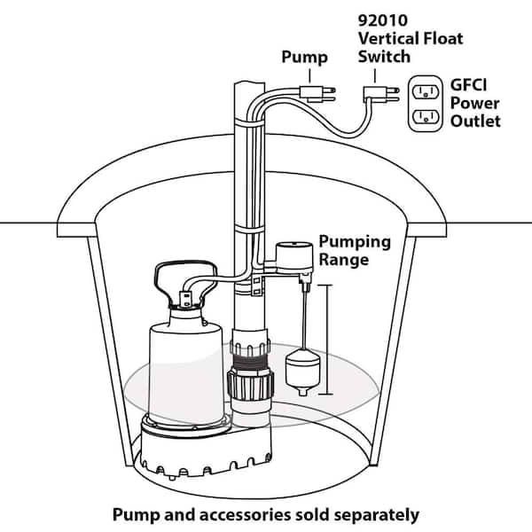
Superior Pump Vertical Float Switch 92010
Septic pump float switch | Electrician Talk If it has two floats, it has a relay in it. white is neutral black is hot and red is switch wire. when the tank fills with water both floats tip up, the short float switches the power to the red wire which starts the pump. when the water level drops the pump turns off when the the long float tips down. The Bitterness of Poor Quality Remains.

Float Limit Switch, Float Level Sensor-Water Level Switches ...
PDF Float Switch Package Instructions - Sump Alarm The above diagrams demonstrate a float switch utilizing the counterweight included in the package. A counterweight may not be necessary in your particular installation. In submersible pump applications, a float switch can be mounted as shown at left using only a wire tie. The Tether Length illustrated in the Figure can be

Septic Control Panels - Wholesale Septic Supply | Wholesale ...
Septic Tank Float Switch: Functions, Types & Problems Types Of Septic Tank Float Switches. There are options when it comes to choosing a more appropriate septic tank float switch for your use. Some of the main variants include submersible sensors, pump duty floats, mechanical sump switches, control duty floats, and horizontal float switches.

Septic Tank Alarm, Float Switch, High Water Alarm, Septic ...

electrical - Correct wiring of float switch into two pole ...
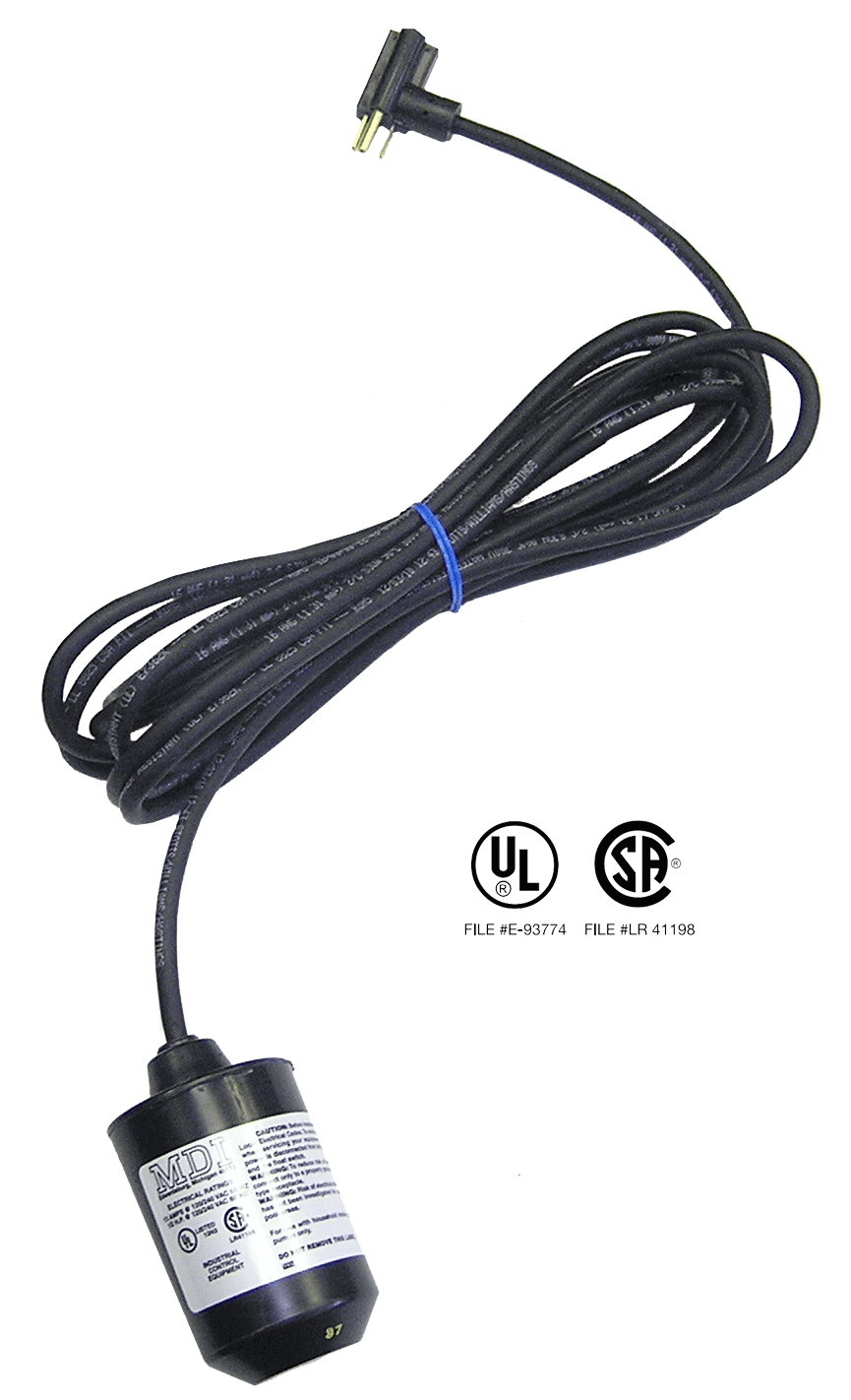
Pump Duty Float Switch - 30 Foot - Normally Open - Wide Angle - 120 VAC Piggyback Plug
Benefits of Time Dosing and Flow Equalization | Onsite Installer

How do I wire a 110 float switch to a 220 pump? Its a 220 v 1 ...

SJE Rhombus Double Float Pump Switch

13 220 well ideas | submersible pump, submersible, well pump
How to Install and Wire a Well Pump - Well Pump Installation ...
Float Switches – Pump Up vs. Pump Down & Normally Open vs ...
Well & Septic Systems Diagnostics - Monticello Well Pump Services
Installation Manual XLSG200 & XLSGX200 Series 2 HP Grinder ...

Liberty Pumps Pro370-Series Simplex Sewage/Grinder Systems ...

Float Switch Installation Wiring & Control Diagrams | APG
Miami University Department of Engineering Technology ENT 498 ...

Wiring Septic Systems: Get the Facts - Griff Electric

float switch wiring diagram for water pump - YouTube ...

We remodel a home and found the electrical bill 50 kwatts per ...

float switch wiring diagram for water pump
Emergency Question - Float switch for septic lift pump ...
ID-164: Steps in Constructing a Pressure Distribution Septic ...
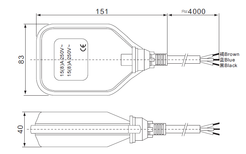
Water Pump 3 Wire Cable High Temperature Float Switch 3m 5m ...
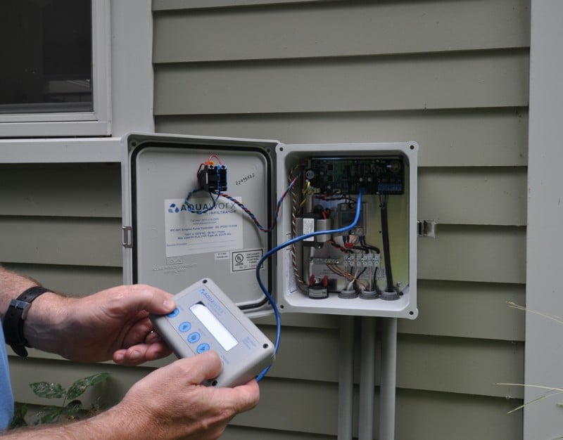
Aquaworx Septic Pump Control Box | Infiltrator
220 wiring/ float switch setup for septic effluent pump ...
HydroCheck HC6000 v2 - Electronic Hi-Lo Pump Switch w/ Dual ...

Float switch - Wikipedia
Sump and Sewage Pump Float Settings


Comments
Post a Comment